| |
TM 10-3930-643-20
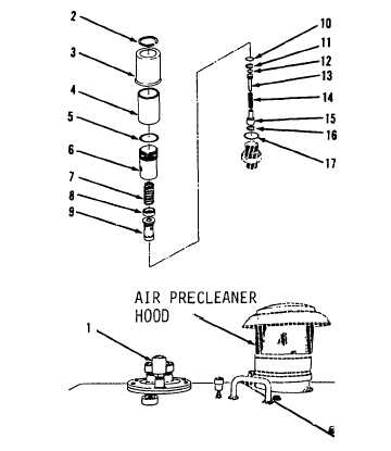
HYDRAULIC SYSTEM TROUBLESHOOTING AND MAINTENANCE.
14-2.
Hydraulic Reservoir Relief Valve. (Sheet 4 of 4)
ASSEMBLY
7.
U s i n g a f l a t t i p s c r e w d r i v e r ,
install new seal (17), ring
( 1 6 ),
g u i d e ( 1 5 ) , s p r i n g ( 1 4 ) , p o p p et
(13), new seal (12), ring (11) and
new seal (10).
8.
I n s t a l l s l e e v e ( 9 ) , r e t a i n er
( 8 ),
spring (7), valve head (6) and new
s e a l ( 5 ).
9.
U s i n g e x t e r n a l s n a p r i n g p l i e r s,
i n s t a l l f i l t e r ( 4 ) , v a l v e c ap
( 3)
and retaining ring (2).
INSTALLATION
10.
Using a 1–1/2” adjustable wrench,
install relief valve assembly (1) at
top of hydraulic reservoir.
NOTE
Return M10A Forklift to original
equipment condition.
END OF TASK
14-7
|