| |
TM 10-3930-643-20
STEERING TROUBLESHOOTING AND MAINTENANCE. (cont)
10-5.
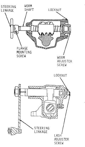
Steering Gear Assembly. (Sheet 4 of 5)
ADJUSTMENT (cont)
Do not turn hard against stops
when
s t e e r i n g l i n k a g e i s
disconnected. Damage to ball
guides inside steering gear may
r e s u l t .
13.
Turn worm shaft to center position.
14.
Using a torque wrench and 1-1/4”
socket, measure pull
r e q u i r e d t o
keep worm shaft in motion through
center position.
Torque value
s h o u l d b e 1 - 1 / 2 t o 5 - 1 / 2 l b - i n . I f
torque value is
o u t s i d e l i m i t s ,
perform adjustments in step 15.
15.
Using a 5/8” socket, socket wrench
handle and flat tip screwdriver,
loosen locknut and turn worm
adjuster screw until required
torque value is reached.
16.
Tighten locknut and recheck torque.
Torque value must be within limits
after locknut is tightened.
17.
Turn lash adjuster screw clockwise
to take out lash in gear teeth
and
tighten locknut.
Go to sheet 5
10-22
|