| |
TM 10-3930-643-20
STEERING TROUBLESHOOTING AND MAINTENANCE.
10-5.
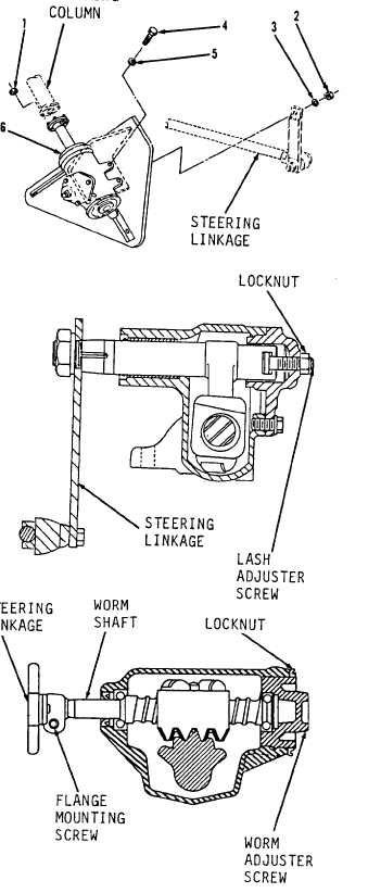
Steering Gear Assembly. (Sheet 3 of 5)
INSTALLATION
6.
U s i n g a 5 / 8 ” s o c k e t a n d s o c k et
wrench handle, install steering gear
assembly (6), three washers (5) and
b o l t s ( 4 ) i n f r o n t o f v e h i c le
beneath cab.
7.
Using a 1-1/4” socket and socket
wrench handle, i n s t a l l l o c k w a s h er
(3) and nut (2).
Tighten nut (2) to
120 to 160 lb-ft.
8.
Using a 1/2” box end wrench, install
two locknuts (1).
SERVICE
9.
Fill steering gear assembly with
oil. Refer to LO 10-3930-643-12.
ADJUSTMENT
10.
11.
12.
NOTE
Adjustments to steering gear must
be made with steering column and
s t e e r i n g l i n k a g e d i s c o n n e c t ed
f r o m s t e e r i n g g e a r . R e f e r to
REMOVAL procedure above. Loosen
flange mounting screw and remove
steering column flange from worm
s h a f t.
Using a 1/2” box end wrench, loosen
locknut.
Using a flat tip screwdriver, turn
lash adjuster screw all the way in
( c l o c k w i s e ) a n d t h e n o u t
( c o u n t e r c l o c k w i s e ) t h r e e t u r n s.
This procedure removes load on worm
bearings from close meshing of rack
and sector teeth.
Using a 1-1/4” socket and socket
wrench handle, turn worm shaft from
one stop all the way to the other
while counting total number of turns.
G O to sheet 4
10-21
|