| |
TM 10-3930-643-20
STEERING TROUBLESHOOTING AND MAINTENANCE. (cont)
10-4.
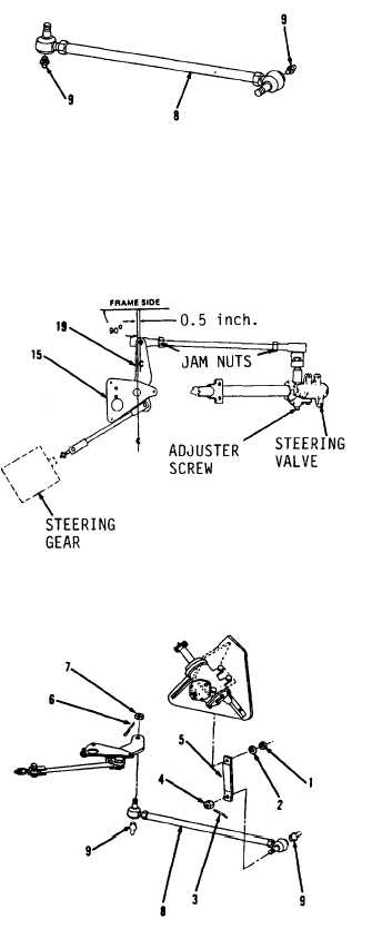
Steering Linkage. (Sheet 6 of 8)
INSTALLATION (cont)
30 l
31.
32.
33.
34.
35.
36.
37.
38.
39.
Using a 5/16” box end wrench, in-
stall two fittings (9) in drag link
assembly (8).
Establish lever assembly (19) center
line at 90 degrees to frame through
pivot point at shaft assembly (15),
as shown.
Position drag link (8) pivot point
0.5 inches forward of center line,
as shown.
U s i n g a 3 / 4 ” s o c k e t a n d s o c k et
wrench handle, install drag
l i n k
assembly (8) and nut (7).
Tighten
nut (7) to 120 lb-ft.
If necessary,
adjust length of drag link assembly
(8) by loosening jam nuts at each
end of rod and turning rod.
Tighten
jam nuts to 80-100 lb-ft.
U s i n g l o n g r o u n d n o s e p l i e r s,
install new cotter pin (6).
U s i n g a 3 / 4 ” s o c k e t a n d s o c k et
wrench handle, install pitman arm
(5) and nut (4).
Tighten nut (4) to
120 lb-ft.
Using long
r o u n d n o s e p l i e r s,
install new cotter pin (3).
Using a 1-5/16” socket and socket
wrench handle, i n s t a l l l o c k w a s h er
(2) and nut (1).
Tighten nut (1) to
120-160 lb-ft.
Check for steering gear free play by
rotating pitman arm (5) back and
forth by hand.
I f a n y f r e e p l ay
exists, pitman arm
nut
must be
loosened and steering gear adjuster
nut tightened, refer to
paragraph
10-5.
I f s t e e r i n g g e a r i s a d j u s t e d,
recheck pitman arm (5) for vertical
position and tighten nut to 120-160
l b - f t .
Go to sheet 7
10-16
|