| |
TM 10-3930-643-20
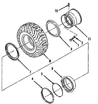
WHEEL TROUBLESHOOTING AND MAINTENANCE.
9-2.
Wheel Assembly and Tire. (Sheet 7 of 8)
CLEANING/INSPECTION
17.
I n s p e c t a l l p a r t s.
R e f e r to
paragraph 2-9.
INSTALLATION
18.
19.
20.
21.
22.
23.
24.
25.
Use two 1-5/16” box and open end
wrenches and install valve (10) in
wheel (11).
Tighten valve (10) to
50 to 55 lb-in.
Position wheel (11) on mounting
stand.
Lock ring (4) side must be
up.
Provide ample clearance from
floor. Tire (8) must rest on wheel
(11) rim.
Install flange (9) on wheel (11)
Drive lug on flange must engage slot
in wheel (11).
Attach hoist and sling to tire (8)
and install on wheel (11).
Install flange (7) on wheel (11).
Drive lug on flange (7) alines with
drive lug on wheel (11).
Install side ring (6) on wheel (11).
Drive lug slot in side ring
(6)
alines with drive lug on flange (7).
Position lock ring (4) in lock ring
(4) gutter. Drive lug in lock ring
(4) alines with slot in gutter of
wheel (11) and slot in
side
r i ng
( 6 ) .
Tap into place with babbit
hammer.
Tap until side ring (6) drops below
preformed packing (5) groove in
wheel (11).
Go to sheet 8
9-9
|