| |
TM 10-3930-643-20
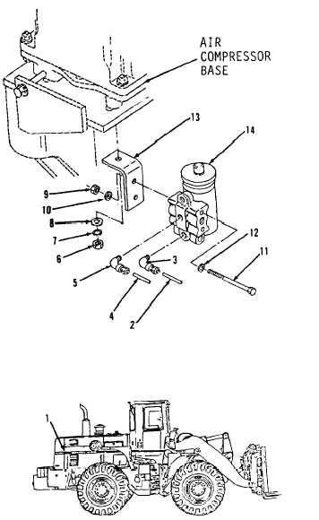
BRAKE TROUBLESHOOTING AND MAINTENANCE. (cont)
8-20.
Governor Assembly. (Sheet 4 of 4)
INSTALLATION
13.
14.
15.
16.
17.
18.
19.
20.
Position governor assembly (14) in
right side of engine.
Using a 1/2” socket, socket wrench
handle and a 1/2” box end wrench,
install angle (13), two washers (12),
bolts (11), washers (10) and nuts (9).
Using a 9/16” socket and socket
wrench handle, install washers (8
and 7) and nut (6).
Using a 7/16” open end wrench,
install elbow (5).
Connect hose assembly (4).
Install elbow (3).
Connect hose assembly (2).
Install engine side access cover (1)
in right side of engine compartment,
refer to paragraph 12-4.
ADJUSTMENT
21.
Start engine and build up air system
pressure.
Note the pressure at which
the governor cuts out.
If pressure
is lower than 105 psi or higher than
125 psi, remove the dust cap on top
of governor.
22.
Using a 3/8” open end wrench, loosen
locknut.
23.
Using a flat tip screwdriver, turn
the adjusting screw counterclockwise
to raise or clockwise to lower the
air pressure.
24.
Using a 3/8” open end wrench, tighten
locknut.
25.
Install dust cap.
NOTE
Return M10A Forklift to original
equipment condition.
END OF TASK
8-124
|