| |
TM 10-3930-643-20
BRAKE TROUBLESHOOTING AND MAINTENANCE. (cont)
8-20.
Governor Assembly. (Sheet 2 of 4)
REMOVAL
Make sure
WARNING
t h a t v e h i c l e w i l l n ot
r o l l o r s h i f t.
Secure with wood
blocks .
DEATH
or serious injury may result by
your failure
t o f o l l o w t h i s
procedure.
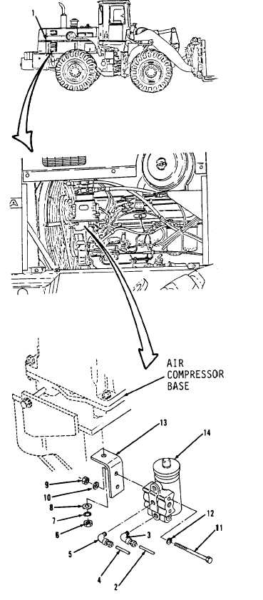
1.
Remove engine side access cover (1)
in right side of engine compartment,
refer to paragraph 12-4.
NOTE
Tag all hose and tube assemblies
2.
3.
4.
5.
6 .
7.
8.
9.
before disconnecting to aid in
i n s t a l l a t i o n.
Using a 7/16” open end wrench,
disconnect hose assembly (2) in
right side of engine.
Remove elbow (3).
Disconnect hose assembly (4).
Remove elbow (5).
Using a 9/16” socket and socket
wrench handle,
remove
n u t ( 6 ) ,
washers (7 and 8) and items 9
thru
14 as an assembly.
Using a 1/2” socket, socket wrench
handle and 1/2” box end wrench, remove
two nuts (9), washers (10),
b o l ts
(11) and washers (12).
Remove angle (13).
Remove governor assembly (14).
Go to sheet 3
8-122
|