| |
TM 10-3930-643-20
BRAKE TROUBLESHOOTING
8 - 8.
Brake Hydraulic
INSTALLATION
AND MAINTENANCE.
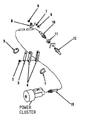
Hoses, Lines and Fittings. (Sheet 10 of 11)
71.
72.
73.
74.
75.
76.
77.
Using 11/16” and 1/2” open end
wrenches, install hose assembly (12)
and nut (11) on right side,
center
o f f o r k l i f t f r a m e.
Using 1/2” and 1“ open end wrenches,
install hose assembly (10).
Using a 9/16” socket and socket
wrench handle, install two
washers
( 9 ) , c l a m p s ( 8 ) , w a s h e r s ( 7 ) a nd
n u t s ( 6 ) .
Install new tie strap (5).
Using a 9/16” box end wrench, install
clamp (4), link (3) and two nuts
( 2 ) .
Install four new tie straps (1) on
l e f t s i d e o f p r e s s u r e c o n v e r t e r/
power cluster.
Using a 3/4” open end wrench, install
h o s e a s s e m b l y ( 1 0 ) t o p r e s s u re
converter/power cluster.
BLEEDING THE BRAKES
NOTE
Each axle has one pair of brakes
and one pressure converter/power
c l u s t e r.
The following is the
maintenance procedure for the
bleeding of one pair of brakes
and one pressure converter/power
cluster. The maintenance procedure
for the remaining pair of brakes
and pressure converter/power cluster
i s i d e n t i c a l .
78.
Check pressure converter/power
cluster fluid level. Remove cap
from reservoir and visually check
l e v e l .
If fluid level is below
1 - 1 / 2 ” f r o m t o p , f i l l r e s e r v o i r.
Refer to LO 10-3930-643-12.
79.
Check to be sure there is adequate
air pressure in the air tanks.
Go to sheet 11
8-34
|