| |
TM 10-3930-643-20
ELECTRICAL SYSTEM TROUBLESHOOTING AND MAINTENANCE.
5-33. Master Disconnect Switch. (Sheet 2 of 3)
REMOVAL
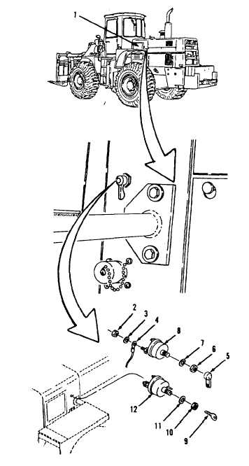
1.
2.
3.
4.
Remove engine side access cover (1)
from
left
side
of
engine
compartment, refer
to paragraph
12-4.
NOTE
A l l e l e c t r i c a l c o n n e c t i o n s,
except those on the instrument
p a n e l , a r e s e a l e d a g a i n st
moisture with silicone sealant.
R e m o v e a l l s i l i c o n e s e a l a nt
before performing maintenance
on electrical connections.
All wire must be tagged when
r e m o v e d f r o m c o n n e c t o r .
I n d i c a t e w h e t h e r w i r e i s
connected
t o p i n - t y p e o r
socket-type connector.
Using a 9/16” open end wrench,
remove two nuts (2) and washers (3)
from rear, left side of vehicle.
Disconnect two wire assemblies
(4)
at terminals.
NOTE
T h e f o l l o w i n g i s a d i f f e r e n ce
between M10A Forklift models.
The removal/installation
procedure is identical.
Using a 1“ open end wrench, remove
knob (5), nut (6), lock washer (7)
a n d s w i t c h ( 8 ) f r o m v e h i c l e s S / N
2001 and above or remove key (9),
nut (10), lock
w a s h e r ( 1 1 ) a nd
switch (12) from vehicles S/N 2000
and below.
Go to sheet 3
5-169
|