| |
TM 10-3930-643-20
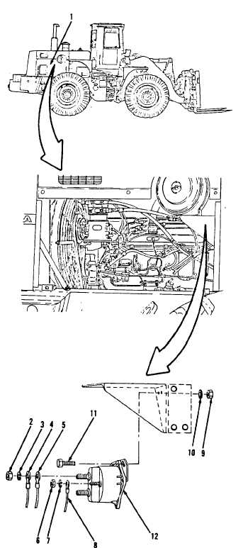
ELECTRICAL SYSTEM TROUBLESHOOTING AND MAINTENANCE.
5-32.
Magnetic Switch. (Sheet 2 of 4)
REMOVAL
1.
2.
3.
4.
Remove engine side access cover (1)
on right side of engine compartment,
refer to paragraph 12-4.
NOTE
A l l e l e c t r i c a l c o n n e c t i o n s , e x c e p t
those on the instrument panel,
are
s e a l e d a g a i n st
moisture
with
s i l i c o n e
sealant. Remove
a l l
silicone sealant
maintenance
on
connections.
All wire must be
from connector.
before
performing
e l e c t r i c a l
tagged when removed
Indicate whether
wire is connected to
p i n - t y p e o r
socket-type connector.
Using a 1/2” open end wrench,
remove
two nuts (2) and lock washers (3).
Disconnect two wire assemblies (4
and 5) at terminals.
Using a 3/8” open end wrench.
remove
two nuts (6) and lock washers (7).
5.
Disconnect two wire assemblies
(8)
at terminals.
G O to sheet 3
5-165
|