| |
TM 10-3930-643-20
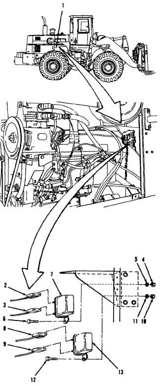
ELECTRICAL SYSTEM TROUBLESHOOTING AND MAINTENANCE. (cont)
5-11.
Starter Lockout Relays. (Sheet 2 of 5)
REMOVAL
1.
Remove engine side access cover (1)
from right side of engine compart-
ment, refer to paragraph 12-4.
NOTE
• A l l e l e c t r i c a l c o n n e c t i o n s ,
except those on the instrument
p a n e l , a re
s e a l e d a g a i n st
moisture with silicone sealant.
R e m o v e a l l s i l i c o n e s e a l a nt
before performing maintenance
on electrical connections.
• A1l wire must be tagged when
2.
3.
4.
5.
removed
from
connector.
I n d i c a t e w h e t h e r w i r e i s
c o n n e c t e d t o p i n - t y p e o r
socket-type connector.
Disconnect wire assemblies (2 and 3)
on right side
f r a m e o f e n g i n e
compartment.
Using a 7/16” open end wrench, 7/16”
socket and socket
wrench handle,
remove two nuts (4), lock
washers
(5), bolts (6) and relay (7).
Disconnect wire assemblies (8 and
9 ) .
Remove two nuts (10), lock washers
(11), bolts (12) and relay (13).
CLEANING/INSPECTION
6.
Wipe all parts with clean cloth
moistened with detergent.
Wipe dry.
Refer to paragraph 2-8.
7.
I n s p e c t a l l p a r t s . R e f e r t o p a r a-
graph 2-9.
Go to sheet 3
5-94
|