| |
TM 10-3930-643-20
ELECTRICAL SYSTEM TROUBLESHOOTING AND MAINTENANCE. (cont)
5-10.
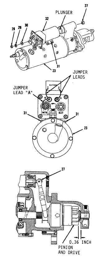
Starting Motor and Solenoid. (Sheet 5 of 7)
TEST/ADJUSTMENT
22.
23.
24.
25.
26.
27.
28.
30.
31•
32.
Position solenoid (32) on plunger.
Using a 7/16” open end wrench,
install four screws (31).
Using a 3/4” open end wrench,
i n s t a l l w a s h e r ( 3 0 ) , l o c k w a s h er
(29) and nut (28).
Using a 9/16” socket and socket
wrench handle, install locknut (27).
Position solenoid (32) and starter
motor (23) in soft jawed vise.
Connect a separate 24-volt battery
as shown using three jumper
leads.
Do not connect
ground
t o m o t o r
terminal at this time.
Momentarily touch jumper lead “A”
from ground to MTR terminal. Drive
will shift into cranking position.
Use feeler gage to measure pinion
clearance. Pinion clearance should
be 0.36 inch.
A d j u s t p i n i o n c l e a r a n c e , i f
necessary by turning locknut (27).
Disconnect three jumper leads.
Go to sheet 6
5-90
|