| |
TM 10-3930-643-20
ELECTRICAL SYSTEM TROUBLESHOOTING AND MAINTENANCE. (cont)
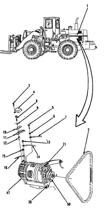
5-9.
Alternator and Alternator Connections. (sheet 2 of 9)
REMOVAL
1.
Remove engine side access cover (1)
from left side of engine compart-
ment, refer to paragraph 12-4.
2 .
Using a cross tip screwdriver,
remove two screws (3) and cover (4).
3.
Using a 1/2”
open end wrench, remove
bolt (5) and washer (6).
•
•
4.
5.
6.
7.
8.
9 .
10.
NOTE
A l l e l e c t r i c a l c o n n e c t i o n s ,
except those on the instrument
panel, are sealed against
moisture with silicone sealant.
Remove all silicone sealant
before performing maintenance
on electrical connections.
All wire must be tagged when
removed from connector.
Indicate whether wire is
connected to pin-type or
socket-type connector.
Disconnect wire assembly
( 7 ) .
Using a cross tip screwdriver,
remove two screws (8), lock washers
(9), plate (10), shield (11) and two
spacers (12).
Using a 9/16” open end wrench, loosen
bolts (21 and 26).
Move alternator
(47) towards engine and slip two
alternator belts (2) off pulley (50).
Using a 7/16” socket and socket
wrench handle, remove nut (13).
Disconnect wire assembly (14).
Remove nut (15).
Disconnect wire assembly (16).
Go to sheet 3
5-78
|