| |
TM 10-3930-643-20
ENGINE, FUEL, EXHAUST AND COOLING TROUBLESHOOTING AND MAINTENANCE. (cont)
4-25.
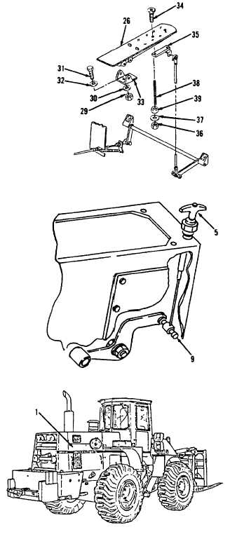
Throttle Control Linkage and Mounting. (Sheet 11 of 11)
ADJUSTMENT
NOTE
Two personnel are required for
adjustment procedure.
61.
62.
63.
64.
65.
66.
67.
68.
69.
Using a 1/2”
socket, socket
wrench
handle and a 1/2” open end wrench,
loosen nuts (39 and 36) and lower
stud (38) from pedal (26).
Depress pedal (26).
Throttle
control must travel its full stroke.
P e d a l ( 2 6 )
W i ll
encounter
r e s i s t a n c e.
Adjust stud (38) to contact Pedal
( 2 6 ).
Using a 1/2”
socket, socket
wrench
handle and a 1/2” open end wrench,
loosen nuts (36 and 39) and lower
stud (38) an additional 1/2 inch.
Tighten nuts (36 and 39).
Depress handle (5) throttle knob on
l o w e r r i g h t s i d e o f i n s t r u m e nt
panel. Operate engine. RPM must be
low .
p u l l h a n d l e ( 5 ) t h r o t t l e a l l
the way out. Engine speed must be
at a minimum of 1200 RPM at no load.
I f a d d i t i o n a l a d j u s t m e n t i s
required, stop the engine.
Be sure
the master disconnect is off.
If required, adjust hand throttle by
loosening screw in connector (9) and
adjusting cable length.
Install engine side access cover (1)
on rear, right
s i d e o f
engine
compartment, refer
to paragraph
12-4.
NOTE
Return M10A Forklift to original
equipment condition.
END OF TASK
4-108
|