| |
TM 10-3930-638-24&P
4-3. FUEL SYSTEM MAINTENANCE (cont)
b. Fuel Injection Pump (cont).
STEP
LOCATION
ITEM
ACTION
REMARKS
REASSEMBLY (cont)
d. Install hydraulic head (81) in fixture on air inlet side of
(cont)
fixture
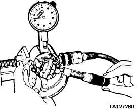
e. Rotate rotor until cam rollers (118) are pushed to their
extreme outward position by air pressure
f. Use a two inch micrometer and measure cam roller-to-cam
roller dimension as shown
g. Dimension shall be 1.965±0.0015 inch; if necessary, turn
adjusting screw (120) clockwise to decrease travel
h. Remove hydraulic head from fixture and install in fixture
P/N 19965
j. Cam ring (116)
Position
On hydraulic head with directional arrow
facing upward
k. Governor weight
Install
Align mark on governor weight retainer
retainer (115)
(1 15) with mark on rotor (123)
l. Retaining ring (114)
Install
Be sure ring is installed in its groove
m. Hydraulic head (81)
Invert in
Be sure governor weight retainer engages
holding
bar on holding fixture
fixture
NOTE
Delivery valves are supplied in standard size and oversize; size used
is etched on rotor.
n. Delivery valve (109)
Install
Be sure it operates freely in its bore
o. Spring (108)
Install
p. New stop (107)
Install
q. Delivery valve
Install
Relieved end facing down; use tool
screw (106)
P/N 13383 and tighten to 85-90 pounds
inch torque
r. Two rotor
Install
Lift hydraulic head up until inside face of
retainers (111)
head is flush with rotor end, then position
with outer sleeve of rotor retaining ring
installation tool P/N 13375
s. Snap ring (1 10)
Install
t. Liner (103)
Install
Install so that large slot is in line with head
locating screw hole and marking indicating
pump rotation is facing upward
4-117
|