| |
TM 10-3930-638-24&P
4-3. FUEL SYSTEM MAINTENANCE (cont)
b. Fuel Injection Pump (cont).
Use tool P/N 13336
STEP
LOCATION
ITEM
ACTION
REMARKS
DISASSEMBLY (cont)
d. Install hydraulic head (81) in fixture on air inlet side of
(cont)
fixture
e, Rotate rotor until cam rollers (118) are pushed to their
extreme outward position by air pressure
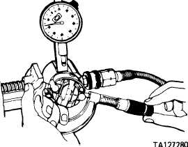
f. Use a two inch micrometer and measure cam roller-to-cam
roller dimension as shown
g. Dimension shall be 1.965 * .0015 inch. Record the dimension
obtained
h. Remove hydraulic head from fixture and install in fixture
P/N 19965
m. Adjusting
Remove
screw (120)
n. Leaf spring (121)
Remove
NOTE
Handle following parts (118, 119, 122, and 123) carefully;
hands must be clean and wet with clean diesel fuel.
o. Two cam
Remove
rollers (118)
p. Two cam
Remove
roller shoes (119)
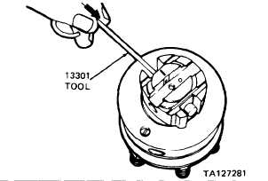
q. Two pumping
Remove
Use extractor P/N 13301 as shown
plungers (122)
4-104
|