| |
TM 10-3930-638-24&P
4-2. ENGINE MAINTENANCE (cont)
h. T1ming Gear Cover (cont).
STEP
LOCATION
ITEM
ACTION
REMARKS
INSTALLATION (cont)
17
(cont)
18
c. Two cap screws (7)
Tighten
Tighten to 3542 pounds foot torque
d. Thrust plate (9)
Check
Use feeler gauge to check running clearance
between thrust plate (9) and idler gear
Idler gear
e. Lock plate (8)
Bend
11)
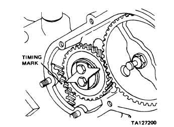
a. Cam gear
Hold
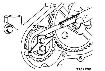
b. Idler gear (11)
Check back-
lash
(11). Clearance must be 0.003 inch. If
clearance is not 0.003 inch remove cap
screws (7), shim(s) (10), thrust plate
(9), and lock plate (8) as an assembly.
Remove and measure thickness of shim(s)
using micrometer. Add or remove shim(s)
as necessary to obtain correct clearance.
Install shim(s), thrust plate, lock plate
and cap screws as an assembly. Tighten
cap screws to 3542 pounds foot torque
Bend tabs on lock plate to lock cap screws
(7)
Use screwdriver
Use dial indicator installed to check back-
lash. Backlash shall not exceed 0.006
inch; if backlash exceeds this dimension,
replace gear (11)
Change 1 4-67
|