| |
TM 10-3930-638-24&P
4-2. ENGINE MAINTENANCE (cont)
f. Pistons and Connecting Rods (cont).
17
STEP
LOCATION
ITEM
ACTION
REMARKS
INSTALLATION (cont)
NOTE
(cont)
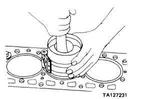
Check that stamped arrow on top of piston (4) is pointed towards
front of engine and numbers on bearing end of connecting rods
(3) face camshaft when performing following step.
b. Piston (4) and
Position
In cylinder bore, halfway in
connecting
rod (3)
NOTE
Check that piston rings (5, 6, and 7) are fully seated in piston (4)
grooves.
c. Piston ring compres-
Install and
On piston (4). Tighten a little at a time,
sor tool
tighten
making sure piston rings are free to
compress
d. Piston (4)
Install
Gently tap down into cylinder block bore
using wooden dowel
e. Piston ring compres-
Remove
sor tool
18
Connecting rod
Bearing liner (12)
Install
Use sliding movement to install; don’t
cap (2)
press on center of liner. Be sure bearing
liner lock is aligned with cap (2) lock
groove
19
Cylinder block,
a. Crankshaft
Clean
Connecting rod journals; use clean
bottom
cloth
b. Plasti gage
Position
Crosswise on connecting rod cap liner (12)
4-50
|