| |
TM 10-3930-638-24&P
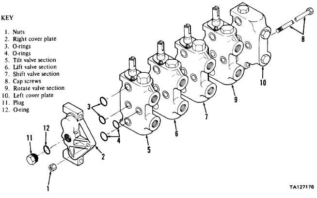
3-30. HYDRAULIC LIFT SYSTEM MAINTENANCE (cont)
a. Control Valve (cont).
STEP
LOCATION
ITEM
ACTION
REMARKS
DISASSEMBLY INTO SECTIONS
4
Right cover
Three nuts (1)
Remove
plate (2)
5
a. Right cover plate (2)
Remove
Lift off cap screws (8)
b. O-rings (3 and 4)
Remove
NOTE
O-rings (3 and 4) are located between valve sections and cover
plates. Remove as valve sections and cover plates are removed.
c. Tilt valve section (5)
Remove
Lift off cap screws (8)
d. Lift valve section (6)
Remove
Lift off cap screws (8)
e. Shift valve section (7)
Remove
Lift off cap screws (8)
f. Three cap screws (8)
Remove
g. Rotate valve section (9) Separate
and left cover plate
(10)
3-207
|