| |
TM 10-3930-638-24&P
3-29. HYDRAULIC LIFT SYSTEM TROUBLESHOOTING (cont)
MALFUNCTION
TEST OR INSPECTION
CORRECTIVE ACTION
2. LOAD DRIFTS DOWN
NOTE
After completion of each check, lower forks
until resting on ground. Then, turn engine
off.
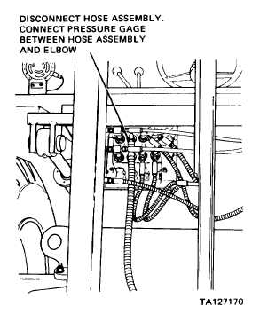
With engine off, operate control levers several times to
relieve hydraulic pressure. Disconnect hose assembly
connected between control valve and lift cylinder
assembly at control valve (refer to illustration).
NOTE
Increase engine speed as necessary to prevent
engine stall.
Connect a 3000 PSI pressure gage between elbow on con
trol valve and hose assembly.
Start engine and place LIFT control lever in RAISE
position until mast assembly is at full height; continue
to hold lever in RAISE position until pressure gage
indicates 2500-2550 PSI with engine at full throttle.
With LIFT control lever in neutral position, observe
pressure gage and mast assembly.
a. If mast assembly drifts down and pressure gage indication does not decrease, remove and repair
lift cylinder assembly (para 3-30e).
b. If pressure gage indication decreases, replace or repair control valve (para 3-30a).
3. UNABLE TO SIDESHIFT LOAD (ALL OTHER FUNCTIONS NORMAL)
NOTE
After completion of each check, turn engine off.
Step 1.
Check sideshift cylinder assembly for hydraulic oil leakage.
a. If hydraulic oil leakage is observed, remove and repair sideshift cylinder assembly (para 3-30c).
b. If hydraulic oil leakage is not observed, proceed to step 2.
Step 2. Check hose assemblies between side shift cylinder assembly and control valve for hydraulic oil leakage.
a. If hydraulic oil leakage is observed at hose assemblies, replace leaking hose assembly (para 2-56 f).
b. If hydraulic oil leakage is not observed at hose assemblies, proceed to step 3.
3-197
|