| |
TM 10-3930-638-24&P
3-24. STEERING SYSTEM MAINTENANCE (cont)
b. Steering Gear (cont).
34
STEP
LOCATION
ITEM
ACTION
REMARKS
REASSEMBLY (cont)
e. Commutator
Position
Position slot side of commutator ring
(cont)
ring (8)
and install
toward housing (43), and lower over
guide studs and onto manifold (9)
f. Seal retainer (5)
Install
Assemble over rotor set (11) and down
and new rotor
against housing (43)
seal (4)
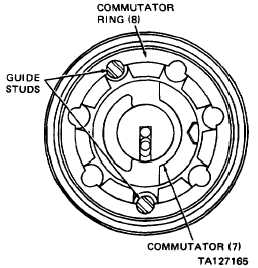
g. Commutator (7)
Position
Position counterbore side of commutator
and install
away from housing (43), and engage
slotted hole in commutator with nose
of drive link (10). Center commutator in
commutator ring to achieve equal spac-
ing as shown
h. Wear washer (6)
Install
Apply a small amount of grease to one side
of washer (6) and place washer over pin
on end cover (3). Grease should hold
washer in place when end cover is
inverted
i. End cover (3)
Position and
Lower end cover (3) over guide studs and
with wear
install
onto commutator ring (8)
washer (6)
j. Five hex bolts (2)
Install and
Tighten hand-tight only
tighten
k. Two guide studs
Remove
l. Two hex bolts (2)
Install and
Tighten hand-tight only
tighten
3-176
|