| |
TM 10-3930-638-24&P
3-24. STEERING SYSTEM MAINTENANCE (cont)
b. Steering Gear (cont).
STEP
LOCATION
ITEM
ACTION
REMARKS
REASSEMBLY (cont)
NOTE
(cont)
Perform the following step only if retainer spring (33) has been
32
removed.
c. New retainer
Install
spring (33)
d. Spring washer (25)
Position
e. Actuator ball (32)
Position
f. Input shaft (27)
Install in
spool (30)
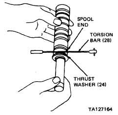
g. Torsion bar (28)
Position
h. Input shaft (27)
with spool (30)
i. Drive ring (31)
Carefully insert into groove on spool to
avoid scratching or nicking spool
Over thrust washer (24) and bearing (23)
In ball seat located inside spool (30)
Hold input shaft and spool in a horizontal
position. Insert input shaft into spool,
engaging the helix and actuator ball with
a counter-clockwise motion
Use mid-section of torsion bar as a gage,
and insert torsion bar between spool end
and thrust washer (24) as shown
Position
Keeping torsion bar between spool end and
vertically
thrust washer, place shaft and spool in a
vertical position, with shaft end on a table
surface
Position and
Position drive ring in end of spool. Visual-
install
ly align an internal space on drive ring wit
a tooth on input shaft spline, and allow
drive ring to drop to limit of its travel.
Rotate input shaft slightly to allow drive
ring to fully engage
3-172
|