| |
TM 10-3930-638-24&P
3-13. STARTER AND SOLENOID REPAIR (cont)
LOCATION
ITEM
ACTION
REMARKS
STEP
ASSEMBLY (cont)
5
(cont)
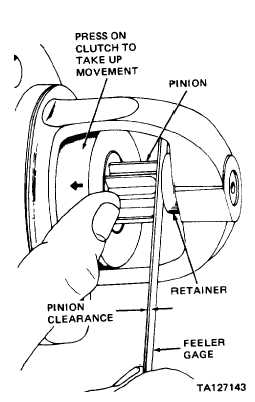
f. Drive assembly (15)
Check
Push clutch back as far as possible toward
pinion
clearance
armature, and check clearance as shown
NOTE
Pinion clearance must measure between
0.010 and 0.140 inch to prevent buttons
on the shift lever yoke (30) from rub-
bing on the clutch collar during crank-
ing. If clearance does not fall within
limits, recheck for proper assembly and
replace all worn parts.
g. Starter and
solenoid
h. Field coil con-
nector (2)
i. Screw (1)
Disconnect
From pinion clearance test set-up
Remove tape
On M terminal of solenoid switch (24)
and position
Install and
Until field coil connector (2) is securely
tighten
mounted
3-113
|