| |
TM 10-3930-638-24&P
3-9.
ALTERNATOR
TROUBLESHOOTING
MALFUNCTION
TEST OR INSPECTION
CORRECTIVE ACTION
1. IMPROPER OUTPUT VOLTAGE
Step 1.
Step 2.
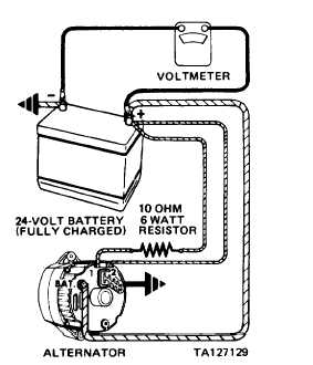
Connect test set-up to alternator as illustrated.
Slowly increase alternator speed and observe voltmeter
reading.
a. If voltmeter reading is uncontrolled with speed, and
increases above 31 Vdc, check alternator field wind-
ing and regulator (para 3-12).
b. If voltmeter indicates battery voltage (no increase
in voltage), proceed to step 2.
c. If voltmeter reading increases (greater than battery
voltage and less than 31 Vdc), proceed to MAL-
FUNCTION 2 (IMPROPER OUTPUT CURRENT).
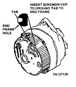
CAUTION
Tab is within 3/4 inch of casting surface. Do not force screwdriv-
er deeper than one inch into alternator end frame.
Insert screwdriver into test hole in end frame and ground
tab as shown; then repeat step 1.
a. If voltmeter indicates battery voltage (no increase
in voltage), check rotor, stator, diode trio, rectifier
bridge, and regulator mounting screws (para 3-12).
b. If voltmeter reading increases, replace the regulator
(para 3-12).
3-89
|