| |
TM 10-3930-638-24&P
3-6. FUEL SYSTEM MAINTENANCE (cont)
c. Fuel Injection Pump (cont).
STEP
LOCATION
ITEM
ACTION
REMARKS
INSTALLATION (cont)
14
cont)
15
NOTE
If engine has been cranked after removing fuel injection pump,
reposition engine at TDC for No. 1 cylinder (para 3-5a(1)).
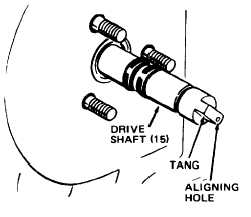
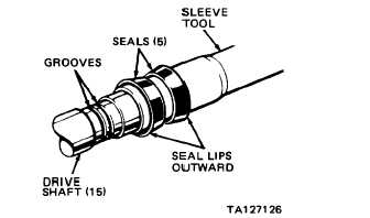
Fuel injection
a. New O-ring (4)
pump (3) and drive b. Two timing window
shaft (15)
screws, cover and
gasket
c. Pump rotor
Position
On injection pump flange
Remove
Position
Using a clean, wide bladed screwdriver at
drive end of injection pump, rotate pump
rotor to approximate position of aligning
hole of tang on drive shaft (15) as shown
below. Then rotate pump rotor until
timing lines in pump window are aligned
NOTE
If holes on drive shaft tang and pump rotor are not aligned,
pump will be 180 degrees out of time.
3-84
|