| |
TM 10-3930-638-24&P
2-48. STEERING SYSTEM MAINTENANCE (cont)
b. Hoses, Lines and Fittings (cont).
(2) Hydraulic Pump to Steering Gear (cont).
STEP
LOCATION
ITEM
ACTION
REMARKS
ADJUSTMENT (cont)
23
24
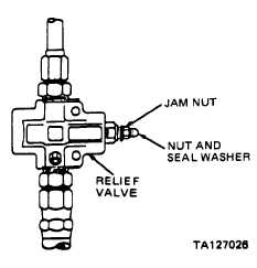
Front chassis,
Relief valve
a. Remove nut
bottom right side
and seal
washer
b. Loosen jam
nut
c. Perform step
22 above
d. Operate engine
at full throttle,
observe pres-
sure gage, and
adjust relief
valve adjust-
ing screw un-
til 2500-2550
PSI indica-
tion is
obtained
e. Tighten jam
nut
f. Reinstall seal
washer and
nut on relief
valve
g. Turn engine
off and per-
form step 20
above
Engine
Hydraulic pump
a. Remove
compartment
pressure gage
b. Install plug or cap
c. Perform step
19 above
Change 2 2-347
|