| |
TM 10-3930-638-24&P
2-26. ALTERNATOR MAINTENANCE (cont)
STEP
LOCATION
ITEM
ACTION
REMARKS
INSTALLATION/REPLACEMENT (cont)
11
h. Cap screw (10), lock
(cont)
washer (9) and nut (8)
i. Cap screw (5), lock
washer (6) and
washer (7)
j. Alternator and fan belt
k. Cap screw (5), nut (8)
and cap screw (16)
l. Wire lead (3), lock
washer (2) and nut (1)
m. Push-on connector (4)
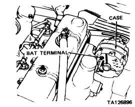
n. BATT terminal of
alternator
o. Resistor (24)
p. Retainer halves (23)
TESTING
12
13
14
Engine compart-
Voltmeter
ment, rear, left
side of vehicle
Install
Install
Adjust
Tighten
Install
Connect
Seal
Position
Push together
and turn
clockwise
Connect
Tighten hand-tight only
Tighten hand-tight only
Para 2-17f
When proper adjustment of alternator and
fan belt is obtained
On BATT terminal of alternator
To alternator terminals 1, 2 and R
Use silicone rubber sealer
In retainer halves (23)
To secure resistor (24)
To alternator BAT terminal and case
ground
Operator’s
a. IGNITION switch
place in ON
compartment
position
b. START switch
Depress and
Operate engine at 1800 RPM with all
start engine
accessories Off
Engine compart-
Voltmeter
ment
Observe
Voltmeter should indicate no more than
31 Vdc with engine operating at 1800
RPM; if indication is more than 31 Vdc,
replace alternator
2-117
|