| |
TM 10-3930-638-24&P
2-23. HORN AND BACK-UP ALARM SYSTEM TROUBLESHOOTING
MALFUNCTION
TEST OR INSPECTION
CORRECTIVE ACTION
1. HORN DOES NOT SOUND
Step 1.
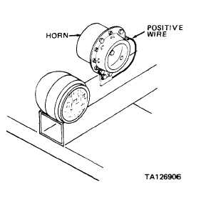
Disconnect positive wire from side of horn.
Connect positive voltmeter lead to connector on
positive wire, and negative voltmeter lead to
vehicle ground.
a. If voltmeter indicates 24 Vdc, reconnect
positive wire to side of horn and proceed to
step 2.
b. If voltmeter does not indicate 24 Vdc,
troubleshoot 25 ampere circuit breaker
(para 2-21, malfunction entry 2, step 6).
If 25 ampere circuit breaker test is
satisfactory, check for open circuit in
wiring between battery positive post and
connector on horn positive wire.
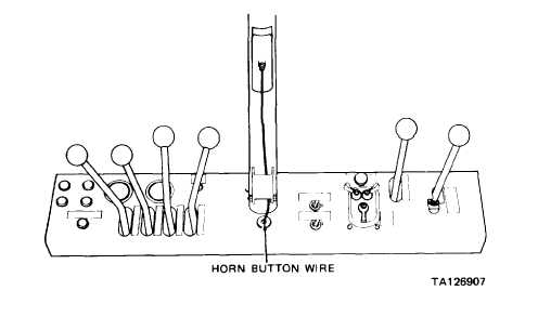
Step 2. Disconnect horn button wire from bottom of horn.
Temporarily connect jumper wire from terminal on bottom of horn to vehicle ground.
a. If horn sounds, reconnect horn button wire to bottom of horn and proceed to step 3.
b. If horn does not sound, replace horn (para 2-32a).
Step 3.
Disconnect horn button wire
from terminal on steering
column. Temporarily connect
jumper wire from connector on
horn button wire to vehicle
ground.
a. If horn does not sound,
check for open circuit in
wire between steering
column and horn.
b. If horn sounds, replace
horn switch (para 2-32b).
2-105
|