| |
TM 10-3930-638-24&P
2-21. STARTING SYSTEM TROUBLESHOOTING (cont)
MALFUNCTION
TEST OR INSPECTION
CORRECTIVE ACTION
2. STARTER FAILS TO CRANK (cont)
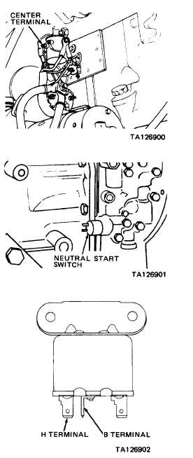
Step 2.
Connect voltmeter leads to center terminal of
starter relay and ground.
Note voltmeter indication while an assistant
depresses START switch.
a.
b .
If voltmeter indicates 24 Vdc,
replace starter relay (para
2-27b).
If voltmeter indicates zero
volts, proceed to step 3.
Step 3.
Connect voltmeter leads to terminals of
neutral start switch.
Note voltmeter indication while an assistant
depresses START switch.
a. If voltmeter indication is a constant
24 Vdc, replace neutral start switch
(para 2-31b).
b. If voltmeter indication is a constant
zero volts, proceed to step 4.
Step 4. Tag and disconnect wires from lockout relay located
at bottom center of instrument panel.
Connect ohmmeter leads to B and H terminals
of lockout relay.
a.
b.
If ohmmeter indicates more than 0.1 ohm,
replace lockout relay (para 2-28d).
If ohmmeter indicates less than 0.1 ohm,
reconnect wires to lockout relay and proceed
to step 5.
Step 5. Connect voltmeter leads to IGN and GRD terminals of IGNITION switch.
With IGNITION switch set at ON, voltmeter should indicate 24 Vdc.
a. If voltmeter does not indicate 24 Vdc, proceed to step 6.
b. If voltmeter indicates 24 Vdc, proceed to step 7.
2-102
|