 |
|||
|
|
|||
|
|
|||
| ||||||||||
|
|
 TM 10-3930-638-24&P
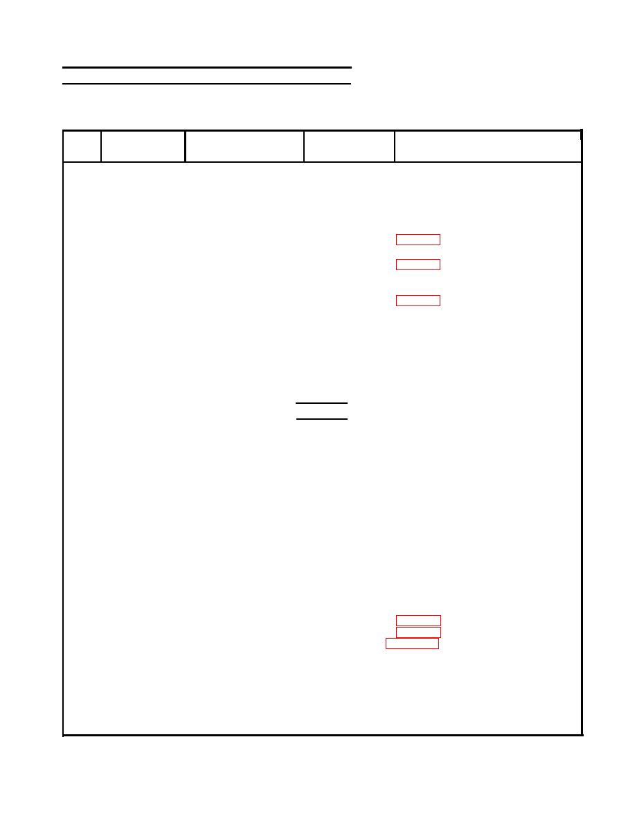
3-31. MAST ASSEMBLY MAINTENANCE (cont)
b. Side Shifter Frame and Rotation Bearing (cont).
REMARKS
ITEM
ACTION
LOCATION
STEP
REMOVAL (cont)
Use chain hoist and move to work area.
Remove
Mast assembly
a. Mast assembly
3
Position mast on two steel horses with
side shifter frame facing up
Remove
b. Rotation cylinder
assembly
Remove
c. Sideshift cylinder
assembly
4
Two sideshift chains
Remove
Side shifter
frame (11),
and pulleys
front
Side shifter
Remove
5
a. 20 cap screws (8),
frame (11),
nuts (9) and
center
washers (10)
To side shifter frame
Secure
b. Chain hoist
WARNING
Be sure chain hoist is securely attached to side shifter frame (11)
before performing following step. Failure to do so could cause
frame (11) to fall causing serious bodily injury.
Remove
c. Side shifter frame (11)
Remove
a. 16 cap screws (12)
Carriage bear-
6
ing plate (14)
NOTE
If cap screws (12) are difficult to remove in above step, heat cap
screws then remove and discard.
Remove
b. Rotation bearing (13)
Remove
c. Four-hose assemblies
Remove
d. Four tube assemblies
Disconnect ends
e. Two lift chains
connected to car-
riage bearing plate
Move half-way out
f. Carriage bearing
of inner mast
plate (14)
Secure to carriage
g. Sling hoist
bearing plate (14)
3-253
|
|
Privacy Statement - Press Release - Copyright Information. - Contact Us |
