 |
|||
|
|
|||
|
|
|||
| ||||||||||
|
|
 TM 10-3930-638-24&P
12-13. GAGES TROUBLESHOOTING (cont)
MALFUNCTION
TEST OR INSPECTION
CORRECTIVE ACTION
1. ENGINE OIL PRESSURE GAGE DOES NOT INDICATE CORRECT PRESSURE (cont)
Step 5.
Disconnect wire from oil pressure sending unit.
Temporarily ground wire while assistant observes oil pressure gage,
Oil pressure gage shall indicate 80 (full scale).
Repair or replace broken wire (notify direct support maintenance).
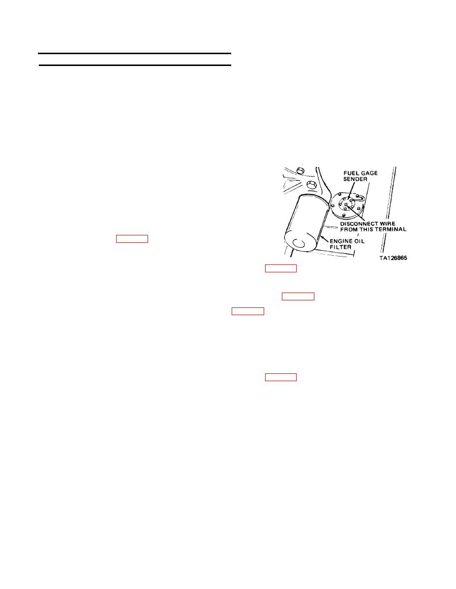
2. FUEL GAGE DOES NOT REGISTER
Step 1.
If fuel gage indicates E, disconnect wire at fuel gage
sender and ground wire to chassis.
Place IGNITION switch in ON position.
Fuel gage should indicate F.
a. If fuel gage indicates F, replace fuel gage sender
b. If fuel gage indicates E, proceed to step 2.
c. If fuel gage indicates other than F or E, replace it (para 2-18b).
Step 2. Check for +24 Vdc at fuel gage IGN terminal (IGNITION switch in ON position),
a. If +24 Vdc not obtained, troubleshoot electrical system (para 2-19).
b. If +24 Vdc obtained, replace fuel gage (para 2-18b).
If fuel gage indicates F, disconnect wire at fuel gage sender.
Step 3.
Fuel gage should indicate E (IGNITION switch ON).
a.. If fuel gage indicates E, replace fuel gage sender.
b. If fuel gage indicates F, repair short circuited wire (notify direct support maintenance)
c. If fuel gage indicates other than F or E, replace it (para 2-18b).
3. FUEL GAGE DOES NOT INDICATE CORRECT FUEL LEVEL
Disconnect wire at fuel gage SENDER terminal and connect a two foot length of no. 22 AWG insulated wire to
this terminal.
Obtain a 1K ohm variable resistor and connect one end to other end of wire connected to fuel gage SENDER
terminal.
Connect center terminal of 1K ohm variable resistor to ground.
Place IGNITION switch in ON position
Adjust variable resistor until fuel gage indicates 1/4 E, turn IGNITION switch OFF, and measure and note
resistance of variable resistor using an ohmmeter.
Turn IGNITION switch ON and repeat this procedure for 1/2 and 3/4 F fuel gage indications.
a. Replace fuel gage if resistance readings are not within 222, 444, and 666 ohms for 1/4 E,
1/2, and 3/4 fuel gage indications.
b. Replace fuel gage sender if resistance readings are within above values.
|
|
Privacy Statement - Press Release - Copyright Information. - Contact Us |
