 |
|||
|
|
|||
|
Page Title:
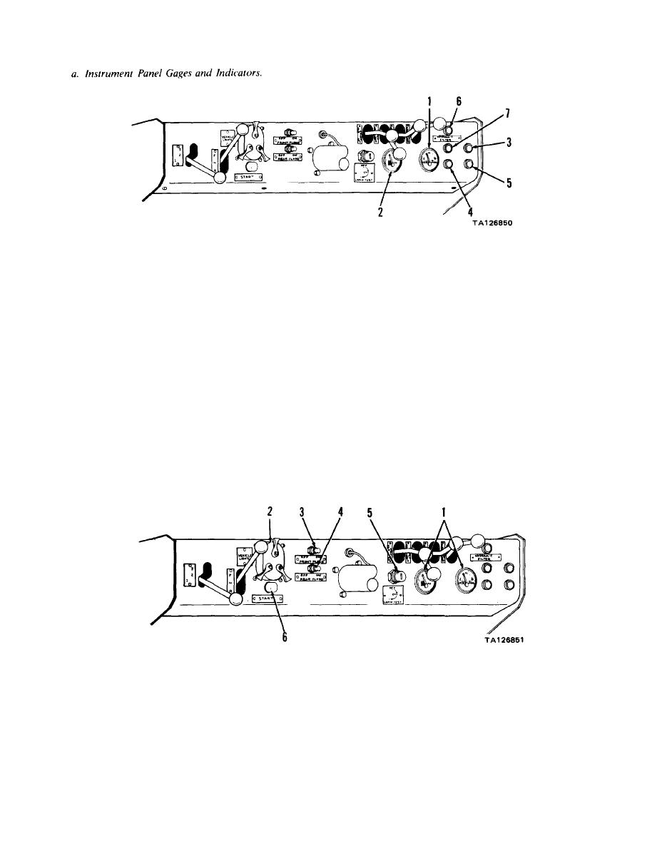
Instrument Panel Switches and Gage Lights. |
|
||
| ||||||||||
|
|
 TM 10-3930-638-24&P
1. OIL PRESSURE GAGE. indicates engine oil pressure
6. HYDRAULIC FILTER INDICATOR. Illuminates
indicating hydraulic filter is clogged and requires replace-
and is electrically connected to engine oil pressure sender
ment; electrically connected to hydraulic filter switch
located on right side of engine.
located in filter head, Indicator illuminates when switch
2. FUEL GAGE. Indicates quantity of fuel in fuel tank;
closes at 20 3 PSI increasing pressure.
electrically connected to fuel level sender located on top
7. TRANSMISSION TEMPERATURE INDICATOR.
of fuel tank.
Illuminates indicating transmission is overheated;
3. ENGINE OIL PRESSURE INDICATOR. Illuminates
electrically connected to transmission temperature switch
indicating low oil pressure; electrically connected to engine
located in right side of transmission. Indicator illuminates
oil pressure switch located on right side of engine near
when switch closes at 265 degrees F.
fuel filters. Indicator illuminates when switch closes at
decreasing pressure of 8 2.5 PSI.
4. ENGINE WATER TEMPERATURE INDICATOR.
Illuminates indicating engine is overheated; electrically
NOTE
connected to engine temperature switch located in cylinder
head. Indicator illuminates when switch closes at 205
HYDRAULIC FILTER, transmission tempera-
degrees F.
ture, and engine temperature indicators will
5. ALTERNATOR INDICATOR. Illuminates indicating
illuminate when ignition switch is placed in
battery is not recharging; connected to terminal I of
LAMP TEST position.
b. Instrument Panel Switches and Gage Lights.
Auxiliary switch controls application of power to gage
lights and brightness of these lights, and power to service
1, GAGE LIGHTS. Provide illumination of oil pressure
tail lights. Mechanical lock prevents main and auxiliary
and fuel gages; lamps are contained within these gages and
switches from applying power to lights except black out
are controlled by VEHICLE LIGHTS switch.
tail lights.
2. VEHICLE LIGHTS SWITCH. Consists of three
3. FRONT FLOOD LIGHTS SWITCH. Applies power
separate sections: main switch, auxiliary switch, and
to illuminate front flood lights.
mechanical lock. Main switch controls application of
4. REAR FLOOD LIGHTS SWITCH. Applies power
power to black out tail and stop light, stop light switch,
to illuminate rear flood lights.
service tail light, and front and rear flood light switches.
1-10
|
|
Privacy Statement - Press Release - Copyright Information. - Contact Us |
