 |
|||
|
|
|||
|
|
|||
| ||||||||||
|
|
 TM 10-3930-634-34
testing, charging, or otherwise servicing the
times to further reduce accumulator pres-
accumulator.
sure, Carefully open bleed valves at each
(1) Check Hydraulic reservoir. Fill, if low.
automatic slack adjuster to bleed off pressure
(2) Turn on ignition. NOTEDO NOT START
to the wheels. Failure to bleed pressure from
VEHICLE.
brake system before servicing or performing
(3) Apply brakes until low pressure warning
maintenance function may result in damage
buzzer sounds. Then apply brakes several more times
to equipment and serious injury to personnel.
to insure all pressure is removed from accumulator.
Use only dry nitrogen gas when servicing the
(4) Turn off ignition.
accumulator.
(5) Bleed pressure off all four slack adjusters.
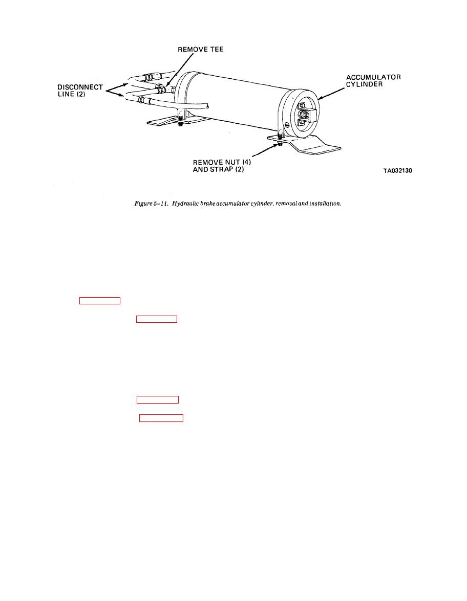
Refer to figure 5-11 and remove the hydraulic brake
(6) Remove panel to gain access to accumulator.
accumulator cylinder.
(7) Remove accumulator guard and cap.
(8) Inspect charging kit for damage.
ble the hydraulic brake accumulator in numerical se-
(9) Close T handle on charging kit hose.
quence.
(10) Turn on nitrogen bottle and set regulator
d. Cleaning and Inspection.
gage to read 275 psi.
(1) Clean the accumulator parts.
(11) Turn off nitrogen bottle.
(2) Inspect hose for deterioration.
(12) Open T handle on charging kit hose to bleed
(3) Inspect piston for scores and scratches.
off pressure.
(4) Inspect strap and body for cracks or any dama-
(13) Attach charging kit to accumulator and open
ge. Replace a defective part.
accumulator valve by holding inner lock nut in place
and turning outer nut.
the hydraulic brake accumulator.
(14) Read regulator gage, if below 275 psi open
charging kit and charge.
the hydraulic brake accumulator cylinder.
(15) Close accumulator valve.
g. Charging the Accumulator. Exercise caution
(16) Close charging kit.
when testing or charging accumulator.
(17) Slowly remove charging hose to bleed pres-
sure.
WARNING
(18) Replace all items removed.
Use only dry nitrogen gas when charging the
(19) Start vehicle and test brakes.
accumulator. Exercise extreme care when
Section IV. STEERING SYSTEM
5-14. GeneraI
modes in four-wheel steer. The turning radius in four-
wheel steer, outside to outside, is 30 feet. In two-wheel
The steering system is fully hydraulic with a me-
steer, outside to outside, the turning radius is 43 feet.
chanical followup. The forklift has two- and four-
It is recommended that four-wheel steer not be used
wheel steering capability, with both crab and cramp
|
|
Privacy Statement - Press Release - Copyright Information. - Contact Us |
