 |
|||
|
|
|||
|
Page Title:
Hydraulic Brake Accumulator Cylinder |
|
||
| ||||||||||
|
|
 TM 10-3930-634-34
sary to exceed 1,900 psi for testing pressure as system
of times, the pressure decreases to a low limit, at
pressure is always less.
which time the accumulator recharges. The pressure is
f. Installation.
the low limit that valve starts to recharge the accumu-
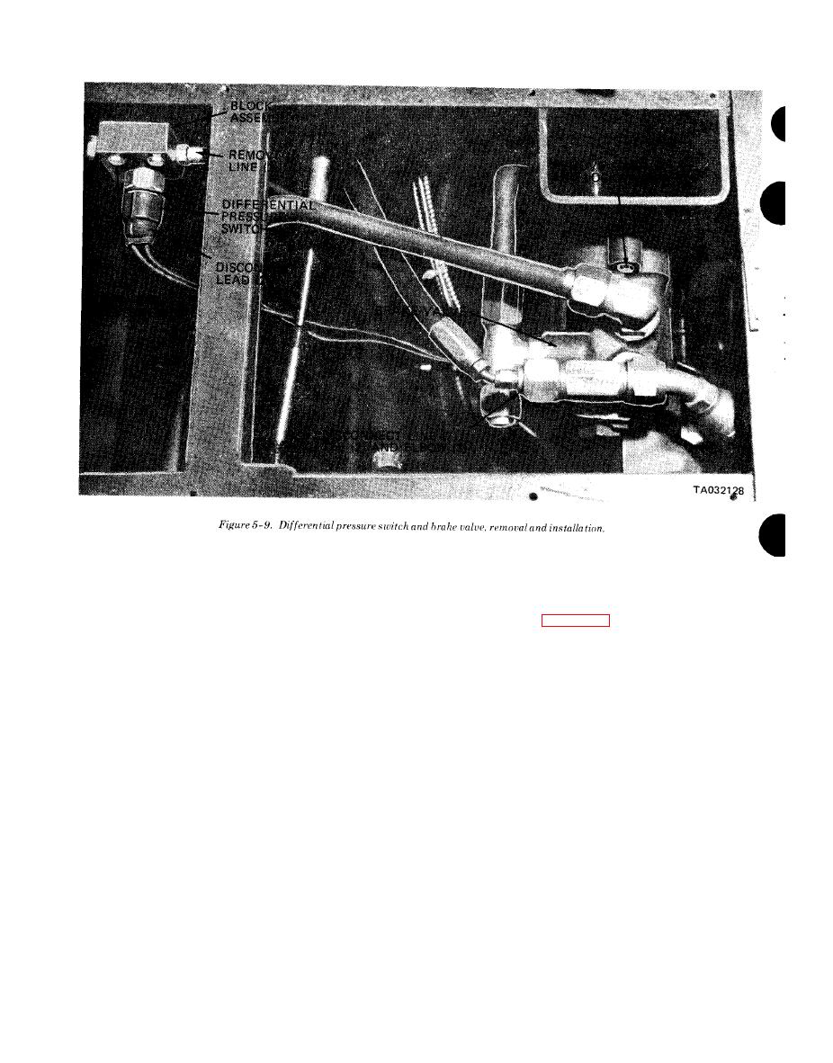
(1) Refer to figure 5-9 and reinstall the brake
lator. The high limit is the adjustable pressure, and
valve.
once this is set automatically, brake valve design de-
(2) Install the access panel under the left fender
termines the low limit or cut in pressure to start the
recharge cycle. The high limit is adjusted by turning
and install driver's floor plate (TM 10-3930-634-12).
the pilot valve adjusting plug (32). One full turn of the
Hydraulic Brake Accumulator
plug changes the limit by 200 psi, turn by 100 psi
Cylinder
and turn on 50 psi The high limit is raised by screw-
ing the plug into the body and lowered by screwing the
a. General. The accumulator is provided to store
plug out of the body.
energy for a limited number of brake applications in
(a) Fill pump with hydraulic oil and attach it to
case the engine stops running. The accumulator cyl-
inder has a free riding piston. Nitrogen is introduced
accumulator port on valve.
(b) Pump up valve until a decisive click is heard,
through a valve on the end of the cylinder to charge
the cylinder. After the cylinder has been charged, oil
caused by shifting of pilot valve, and note gage read-
from the hydraulic system enters the cylinder at the
ing. The reading should be 1,300 psi; if not, adjust the
opposite end, forcing the piston toward the nitrogen,
pilot valve plug (32).
(c) After adjusting high limit pressure, let the
compressing the nitrogen to approximately 1,300 psi.
h. Removal.
pressure leak down until another click is heard when
the low pressure reaches between 650-550 psi.
WARNING
(3) While pressure testing valve, check for leak-
Bleed the brake system pressure by repeated
age. Leakage from either the brake port or return port
application of the brakes with the engine
should be less than 60 drops per minute. No leakage is
stopped, until the low pressure warning buz-
permissible from the pressure plug (38). It is not neces-
zer sounds. Continue to apply brakes several
|
|
Privacy Statement - Press Release - Copyright Information. - Contact Us |
