 |
|||
|
|
|||
|
Page Title:
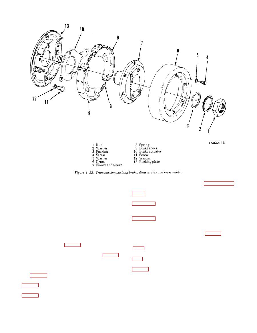
Figure 4-32.transmission parking brake, disassembly and reassembly |
|
||
| ||||||||||
|
|
 TM 10-3930-634-34
transmission case as shown in figure 4-36.
passageway for oil Under pressure to enter the shaft.
(7) Remove rear cover from transmission case (fig.
Oil pressure sealing rings are located on the clutch
shaft to direct oil under pressure to a desired clutch.
(8) Remove low clutch rear bearing as shown in
Pressure of the oil forces the piston and discs against
the heavy backup plate. The discs, with teeth on the
(9) Remove fourth speed clutch assembly by with-
outer diameter clamping against discs with teeth on
drawing toward rear of transmission as shown in
the inner diameter, enable the hub and clutch shaft to
be locked together and allow them to drive as a unit.
NOTE
(4) There are bleed balls on the clutch piston
Do not lose rear bearing lock ball.
which allow quick escape for oil when the pressure to
(10) Remove low speed drive gear (fig. 4-40, A).
the piston is released.
(11) Carefully grasp the reverse and third speed
b. Removal. Remove the transmission assembly
clutch and withdraw from transmission case (fig.
from the forklift truck (para 2 -6).
4-40, B).
c. Disassembly into Subassemblies.
(12) Remove the low clutch as shown in figure
(1) Remove transmission control valve (para 4-7).
(2) Remove transmission parking brake (para
(13) Block output shaft and remove flange nut (1,
4-8).
(3) Remove input shaft flange and front cover
(4) from the disconnect shaft (16).
plug (fig. 4-33).
(14) Remove four screws (5), washers (6) and re-
(4) Remove front cover from transmission case
move disconnect assembly from the transmission.
(15) Remove preformed packing (8) from the dis-
(5) Remove input shaft and gear from front cover
connect housing (7).
(16) Remove shim (9) and oil seal (10).
(6) Carefully grasp the forward and second clutch
(17) Remove cup plug (11) for access to setscrew
assembly and withdraw from the front end of the
|
|
Privacy Statement - Press Release - Copyright Information. - Contact Us |
