 |
|||
|
|
|||
|
Page Title:
Transmission Clutch Packs, Gears,and case |
|
||
| ||||||||||
|
|
 TM 10-3930-634-34
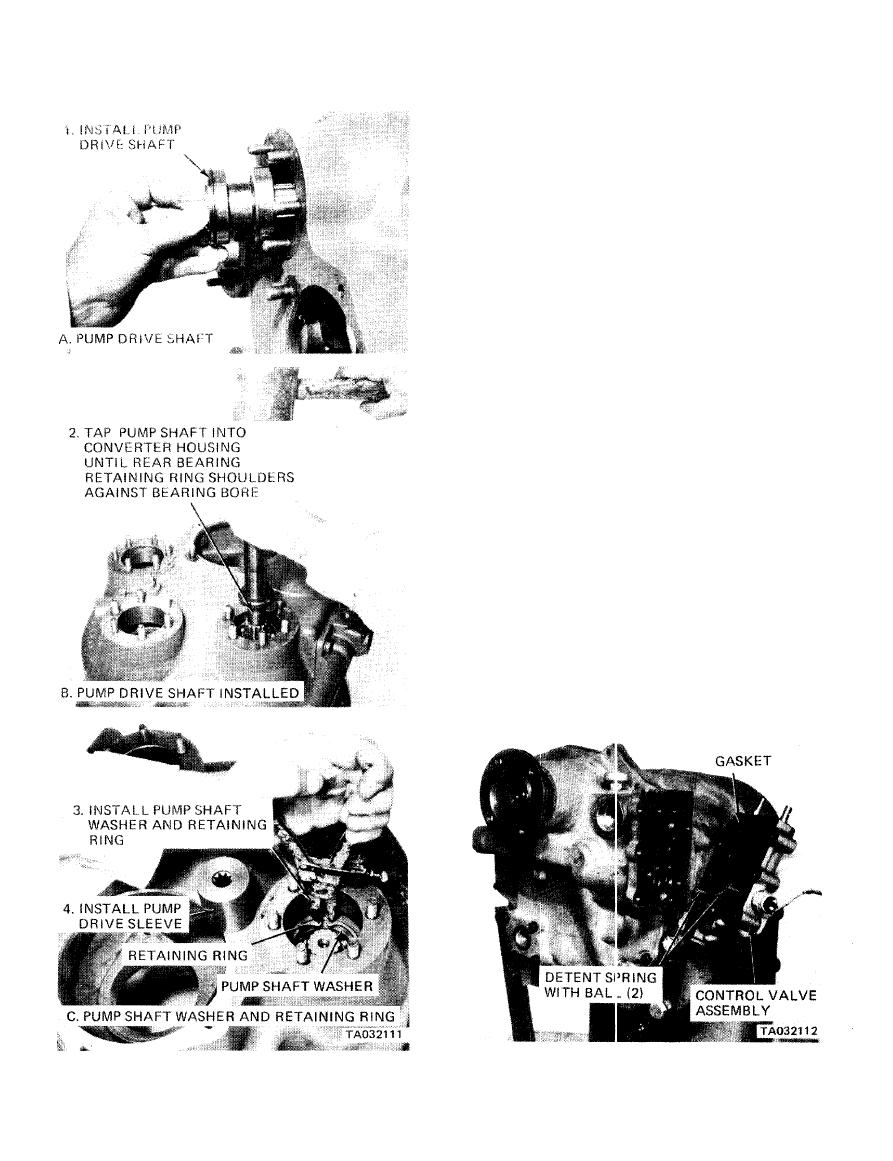
4-9. Transmission Clutch Packs, Gears,
and Case.
a. General.
(1) With the engine running and the direction con-
trol lever in neutral position, oil pressure from the
torque converter regulator valve is blocked at the
transmission control valve and the transmission is in
neutral. Movement of the transmission control valve
forward and reverse spool will direct oil under pres-
sure to either the forward or reverse direction clutch
as desired. When either direction clutch is selected,
the opposite clutch is relieved of pressure and vents
back through the transmission control valve direction
selector spool. The same procedure is used in the speed
selector.
(2) The direction or speed clutch assembly con-
sists of a drum with internal splines and a bore to
receive a hydraulically actuated piston. The piston is
oil tight by the use of sealing rings. A steel disc with
external splines is inserted into the drum and rests
against the piston. Next, a bronze disc with internal
splines is inserted. Discs are alternated until the
required total iS achieved. A heavy backup plate is
then inserted and secured with a snap ring. A hub with
outside diameter splines is inserted into the splines of
discs with teeth on the inner diameter. The discs and
hub are free to increase in speed or rotate in the oppo-
site direction as long as no pressure is present in that
specific clutch.
(3) To engage the clutch, the control valve is
placed in the desired position. This allows oil under
pressure to flow from the control valve, through a
tube, to a chosen clutch shaft. This shaft has a drilled
|
|
Privacy Statement - Press Release - Copyright Information. - Contact Us |
