 |
|||
|
|
|||
|
|
|||
| ||||||||||
|
|
 TM 10-3930-634-34
NOTE
Lip of oil seal (9, fig. 4-22) must be facing in-
ward when installed. Oil seal shall be pressed
five sixteenths of an inch below rear face of
bearing retainer.
C).
(d) Secure output shaft gear in a vise equipped
with soft jaws. Install output flange, new packing,
flange washer, and nut. Tighten nut to 200-250 lb-ft
torque. Install cotter pin.
(4) Stator Support. Reassemble stator support
g. Installation.
NOTE
Immerse gaskets and packings in clean trans-
mission oil.
(1) Install three pump drive shafts (fig. 4-28).
(2) Install pump adapters in reverse of numerical
sequence shown in figure 4-19.
(3) Install stator support (fig. 4-16).
(4) Install output shaft (fig. 4-18). Tighten screws
to specified torque.
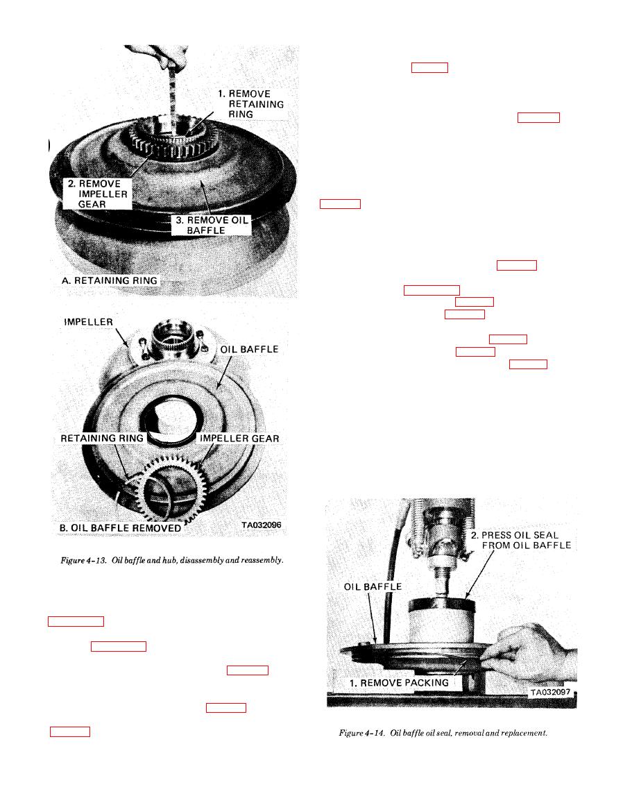
(5) Install impeller and oil baffle (para 4-4).
(6) Install charging pump (para 4-3).
(7) Install torque converter assembly (para 2-7).
(1) Converter Housing. Reassemble the converter
housing in reverse of numerical sequence as shown in
(2) Pump Shafts. Reassemble the pump shafts as
shown in figure 4-25.
(3) Output Shaft.
bearing retainer (8).
(b) Apply a thin coat of permatex No. 2 or equiv-
alent on outer diameter of seal (9, fig. 4-22) to assure
an oil tight fit. Press oil seal (9) in bearing retainer (8)
(fig. 4-26, A).
|
|
Privacy Statement - Press Release - Copyright Information. - Contact Us |
