 |
|||
|
|
|||
|
|
|||
| ||||||||||
|
|
 TM 10-3930-634-34
(9) Install the flywheel housing (para 3-33).
(4) Install capscrew (3, fig. 3-126) and tighten to
(10) Install the engine (para 2-5).
30 to 35 lb-ft of torque. Remove the two pilot cap-
screws installed above.
3-37. Crankshaft and Main Bearings
(5) Lubricate the idler gear hub and idler gear
a. General.
bearings with clean engine oil.
(1) The crankshaft is a one-piece steel forging,
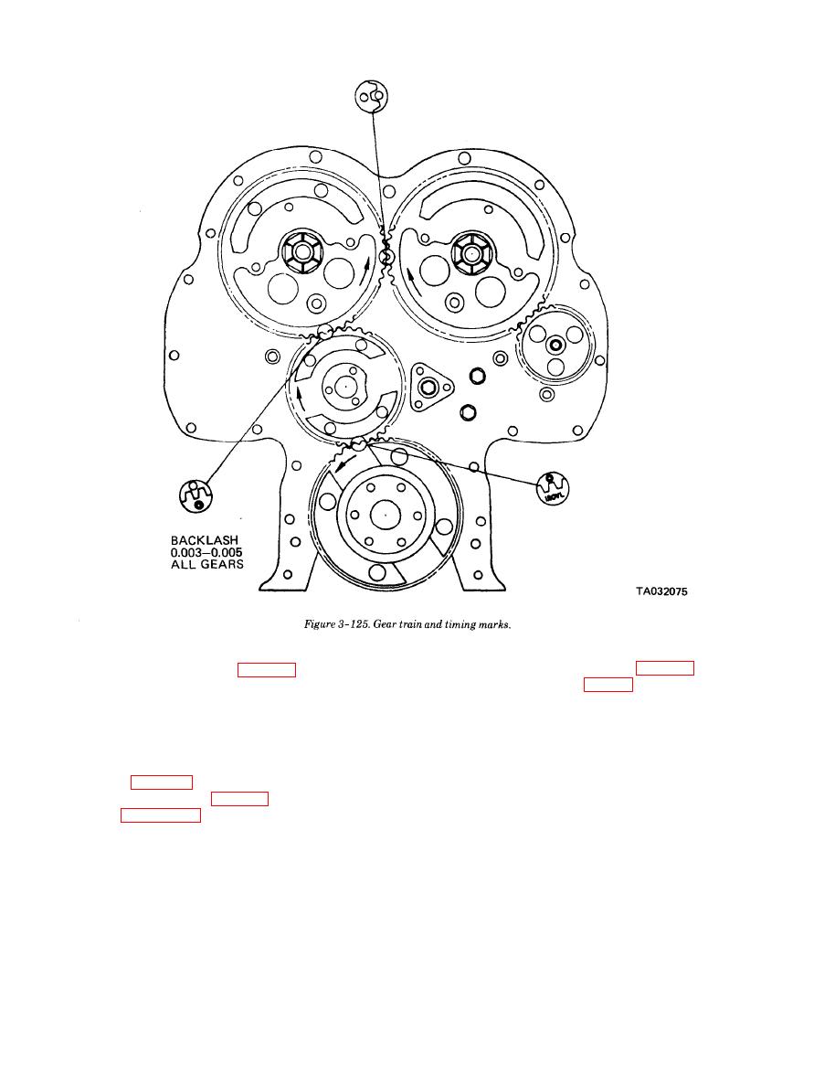
(6) Position the crankshaft gear and the camshaft
heattreated to insure strength and durability. All main
gear so the timing marks will aline with those on the
and connecting rod bearing journal surfaces and oil
idler gear (fig. 3-125). With these marks in alinement,
seal surfaces are induction hardened. Complete static
install the idler gear (6, fig. 3-126) on the hub (5) as
and dynamic balance is achieved by counterweights.
shown in figure 3-128.
(2) The main bearing shells are of the precision
(7) Apply a thin film of cup grease to the inner
type and may be readily replaced without machining.
face (face with the oil grooves) of the outer thrust
They are used at each crankshaft main journal and
washer (4). Place the thrust washer over the hub with
consist of an upper shell seated in the cylinder block
grooves toward the gear and the flat in the inside di-
main bearing support and a lower shell seated in the
ameter of the thrust washer over the flat on the gear
main bearing cap. Bearing shells are prevented from
hub.
endwise or radial movement by a tang at the parting
(8) Check the backlash between the mating gears.
line at one end of each shell. The bearing caps are num-
The backlash should be 0.003 to 0.005 inch between
bered 1, 2, 3 and 4, indicating their respective position
new gears and should not exceed 0.007 inch between
and, when removed, must always be reinstalled in
used gears.
|
|
Privacy Statement - Press Release - Copyright Information. - Contact Us |
