 |
|||
|
|
|||
|
Page Title:
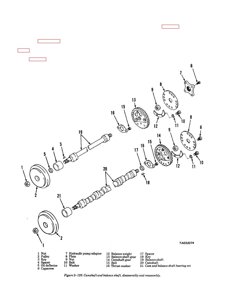
Figure 3-120. Camshaft and balance shaft, disassembly and reassembly |
|
||
| ||||||||||
|
|
 TM 10-3930-634.34
(6) Apply a light coat of cup grease to outside di-
(2) Carefully install the shafts into the cylinder
ameter of seal spacer (4, fig. 3-120) and oil deflector
block being careful not todamage the bearings, cam
(5) and slide on balance shaft.
lobes or journals.
(7) Position keys (3) in shaft keyways. Aline key-
(3) Make sure the timing marks are in alinement
way of pulleys (2) and install on camshafts. It may be
as shown in figure 3-125.
necessary to tap the pulleys to seat them properly; sup-
(4) Install oil slingers on shafts (19 and 20, fig.
port the gear end of shafts when taping pulleys. Install
pulley nuts (l).
(5) Install the engine top front cover with a new
(8) Secure thrust washers (16) in place with
gasket (fig. 3-119).
|
|
Privacy Statement - Press Release - Copyright Information. - Contact Us |
