 |
|||
|
|
|||
|
|
|||
| ||||||||||
|
|
 TM 10-3930-634-34
threads or evidence of overheating. Replace if cracked
or it has been overheated. Chase damaged threads
with the correct size tap or die.
(3) Examine ring gear teeth fordefects ormissing
teeth.
e. Reassembly.
(1) If the ring gear was removed, install the new
ring gear by supporting the flywheel, ring gear side
up, on a solid flat surface.
CAUTION
Do not under any circumstances heat the
gear over 400F; excessive heating may
destroy the original heat treatment.
(2) Rest the new ring gear on a flat metal surface
and heat the gear uniformly with an acetylene torch,
keeping the torch moving around the gear to avoid hot
spots.
(3) Use a pair of tongs to place the gear on the fly-
wheel with the chamfer, if any, facing the same direc-
tion as on the gear removed.
of flywheel with holes in end of crankshaft.
(4) Tap the gear in place against the shoulder on
(2) Install scuff plate securing with capscrews.
the flywheel. If the gear cannot be tapped into place
Tighten capscrews to 110-120 lb. ft. of torque.
readily rem ove it and apply additional heat, heeding
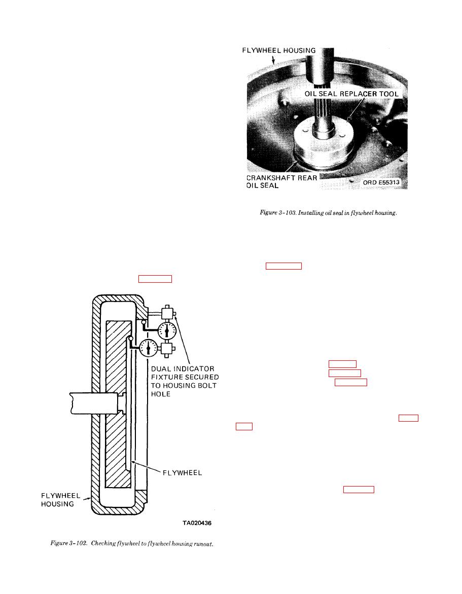
(3) Check the runout of the flywheel to flywheel
the caution about overheating.
housing (fig. 3-102). Maximum allowable runout is
f. Installation.
0.005 inch total indicator reading throughout one
(1) Install the flywheel (fig. 3-101) alining holes
revolution of the flywheel.
3-33. Flywheel Housing
a. General. The flywheel housing is a one-piece cast-
ing mounted against the rear end of the cylinder block.
The housing provides protection for the gear train and
flywheel. The housing also supports the starting
motor.
b. Removal.
(2) Remove the oil pan (para 3-26).
(3) Remove the flywheel (para 3-32).
(4) Remove the fuel pump (TM 10-3930-634-12).
(5) Remove the engine driven hydraulic pump
(TM 10-3930-634-12).
(6) Remove the limiting speed governor (para
(7) Remove the fuel and hydraulic pump drive
(TM 10-3930-634-12).
(8) Remove the breather (TM 10-3930-634-12).
(9) Thread eyebolts into tapped holes in pads on
top or sides of flywheel housing. Attach a suitable
sling and chain hoist to the eyebolts.
(10) Remove three bolts (5, fig. 3-101).
(11) Remove one bolt (6) and washer (7).
(12) Remove two bolts (8) and four bolts (9).
(13) Remove five screws (10) and washers (11).
(14) Thread two pilot studs in the holes located
about the center of the crankshaft, from which screws
were removed.
|
|
Privacy Statement - Press Release - Copyright Information. - Contact Us |
