 |
|||
|
|
|||
|
|
|||
| ||||||||||
|
|
 TM 10-3930-634-34
(4) Measure the clearance between the inner and
outer rotors at each lobe (fig. 3-98, A). The clearance
should not be less than 0.004 inch or more than 0.011
inch.
(5) Measure the clearance from the face of the
pump body to the side of the inner and outer rotor (fig.
inch or more than 0.0035 inch.
(6) Inspect the splines of the inner rotor and the
drive gear. If the splines are excessively worn, replace
the parts.
(7) The rotors are serviced as matched sets; there-
fore, both rotors must be replaced as a set.
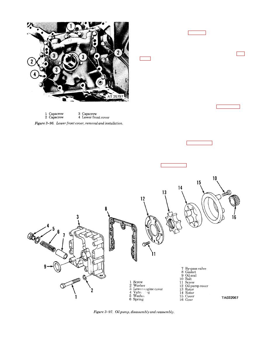
e. Reassembly.
(1) Reassemble the front cover and oil pump in re-
verse of numerical sequence as shown in figure 3-97.
(2) Apply a thin coat of non-hardening sealant to
periphery of oil seal (9). Position front cover (3) inner
face down in an arbor press and press seal with cup
side facing inward into cover until seal is flush with
outer face of cover.
(2) Clean all gasket material from the front cover
(3) If the oil pump drive gear was removed from
and the engine.
the crankshaft refer to figure 3-99 and install the
(3) Inspect the lobes and faces of the rotors for
drive gear,
scratches or burrs and the surfaces of the pump body
f. Installation.
and cover plate for scoring. Scratches, burns or score
(1) Install the lower front cover and oil pump as il-
marks may be removed with a soft stone or crocus
lustrated in figure 3-100, using a new gasket.
cloth.
|
|
Privacy Statement - Press Release - Copyright Information. - Contact Us |
