 |
|||
|
|
|||
|
Page Title:
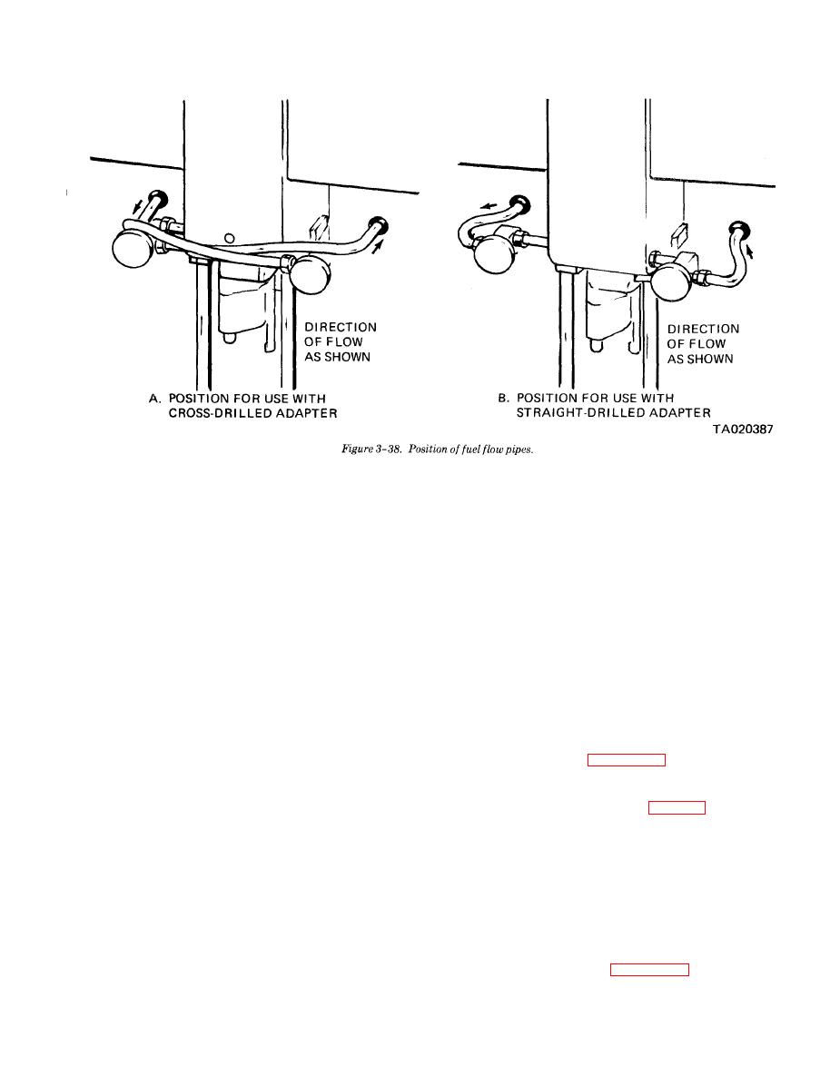
Figure 3-38. Position of fuel flow pipes |
|
||
| ||||||||||
|
|
 TM 10-3930-634-34
force exerted by the governor low speed spring. When
through the spring cap, while the other end provides a
moving fulcrum on which the differential lever pivots.
the governor throttle control lever is placed in the idle
position, the engine will operate at the speed where
(3) When the centrifugal force of the revolving
the force exerted by the governor low speed weights
governor weights balances out the tension on the high
will equal the force exerted by the governor low speed
or low speed spring (depending on the speed range),
spring.
the governor stabilizes the engine speed for a given
(9) Adjustment of the engine idle speed is accom-
setting of the speed control lever.
plished by changing the force on the low speed spring
(4) In low speed range, the centrifugal force of the
low-and-high-speed weights together operates against
by means of the idle adjusting screw.
the low speed spring. As the engine speed increases,
(10) The engine maximum no-load speed is de-
termined by the force exerted by the high speed
the centrifugal force of the low and high speed weight
together compresses the low speed spring until the low
spring. When the governor throttle control lever is
placed in the maximum speed position the engine will
speed weights are against their stops, thus limiting
operate at the speed where force exerted by the
their travel, at which time the low speed spring is fully
governor high speed weights will equal the force ex-
compressed and the low speed spring cap is within
0.0015 inch of the high speed plunger.
erted by the governor high speed spring. Adjustment
of the maximum-no-load speed is accomplished by
(5) Throughout the intermediate speed range the
changing the tension on the high speed spring.
operator has complete control of the engine because
c. Removal. Refer to figure 3-58 and remove the
both low speed spring and low speed weights are not
governor.
exerting enough force to overcome the high speed
(1) Disconnect linkage to governor control levers.
spring.
(2) Remove rocker arm cover (para 3-16).
(6) As speed continues to increase, the centrifugal
(3) Disconnect fuel rod from injector control tube
force of the high speed weights increases until this
lever. Remove clip holding fuel rod to differential
force can overcome the high speed spring and the
lever.
governor again takes control of the engine, limiting
(4) Disconnect fuel lines from fuel pump and re-
the maximum engine speed.
move fuel pump (TM 10-3930-634-12).
(7) A fuel rod is connected to the differential lever
(5) Loosen hose clamp.
and injector control tube lever through the control
(6) Remove five bolts from governor weight hous-
link. This arrangement provides a means for the
ing and two bolts from governor control housing.
governor to change the fuel settings of injector control
(7) Remove governor and gasket from engine.
racks.
(8) The engine idle speed is determined by the
3-37
|
|
Privacy Statement - Press Release - Copyright Information. - Contact Us |
