 |
|||
|
|
|||
|
Page Title:
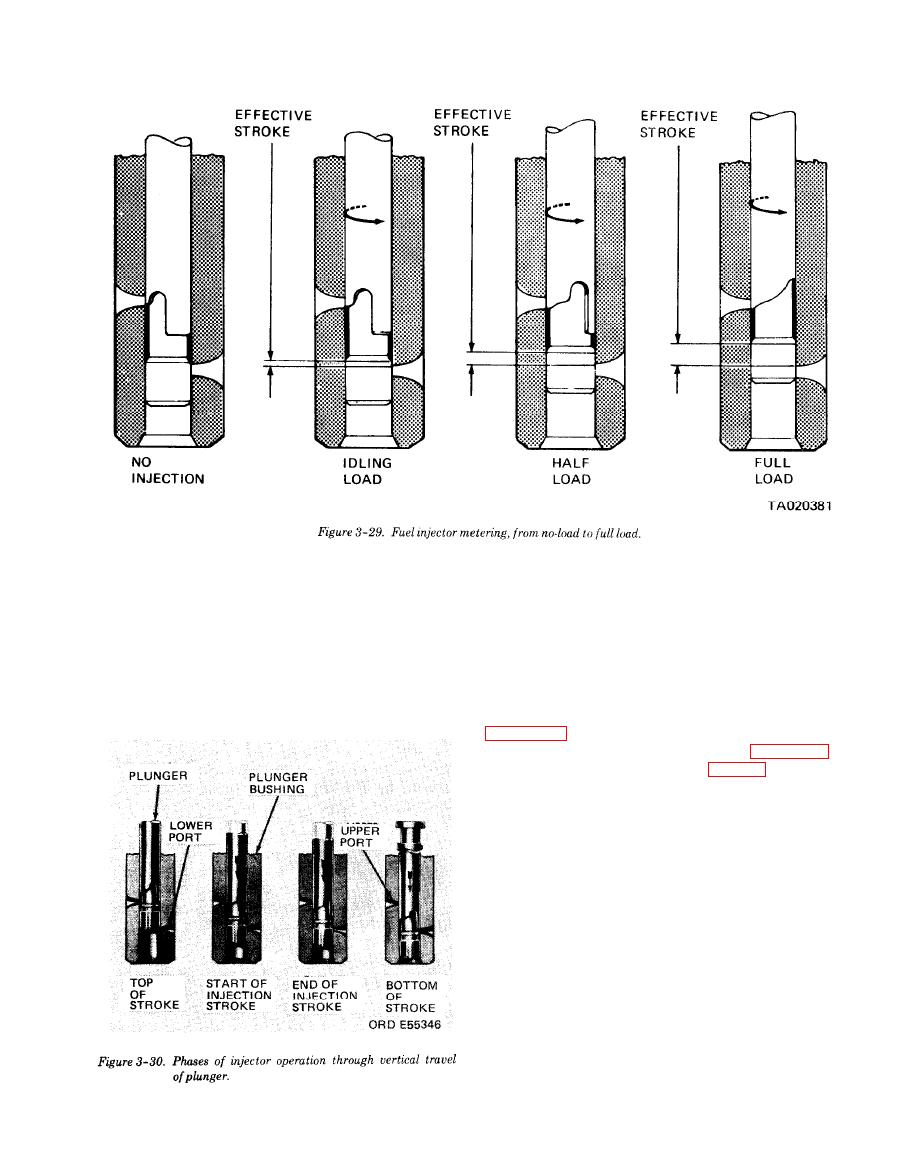
Figure 3-29.Fuel injeto metering,from no-load to full load. |
|
||
| ||||||||||
|
|
 TM 10-3930-634-34
and the cover for scratches, nicks, burrs or other
f. Inspection.
damages which may result in pressure leaks. The
(1) Discard oil seals.
mating surfaces must be flat and smooth and fit tight-
(2) Inspect the pump gear teeth for scoring, chip-
ly together. Replace the cover or body as necessary.
ing, or wear. Inspect the ball slot in the drive gear for
(5) The relief valve must be free from score marks
wear. If any of these conditions are found, replace the
and burrs. If the relief valve is scored and cannot be
damaged or worn parts.
cleaned up with fine emery cloth or crocus cloth it
(3) Inspect the drive and driven shafts for scoring
must be replaced.
or wear. Replace as necessary. The driven shaft is serv-
g. Reassembly.
iced as gear and shaft assembly only.
(1) Install inner oil seal in pump body as shown in
(4) Inspect the mating surfaces of the pump body
(2) Install outer oil seal as shown in figure 3-57.
(3) Clamp the pump body (5, fig. 3-54) in a bench
vise (equipped with soft jaws) with the relief valve
cavity up. Lubricate the outside diameter of the relief
valve (20) and place the valve in the cavity, hollow end
up. Insert the spring (18) inside the valve and the pin
(19) into the spring. With the gasket (17) in place, next
to the head of the valve plug (16), place the plug over
the spring and thread it into the pump body.
(4) Lubricate the pump shaft (11) and insert the
square end of the shaft into the opening at the gear
side of the pump body and through the two oil seals.
(5) Place the drive gear shaft (10) into the pump
body with the chamfered end of the gear teeth facing
the pump body,
(6) Lubricate the gears and shafts with clean
engine oil.
(7) Apply a thin coat of sealer on the face of the
pump cover outside of the gear pocket area, then place
3-33
|
|
Privacy Statement - Press Release - Copyright Information. - Contact Us |
