 |
|||
|
|
|||
|
Page Title:
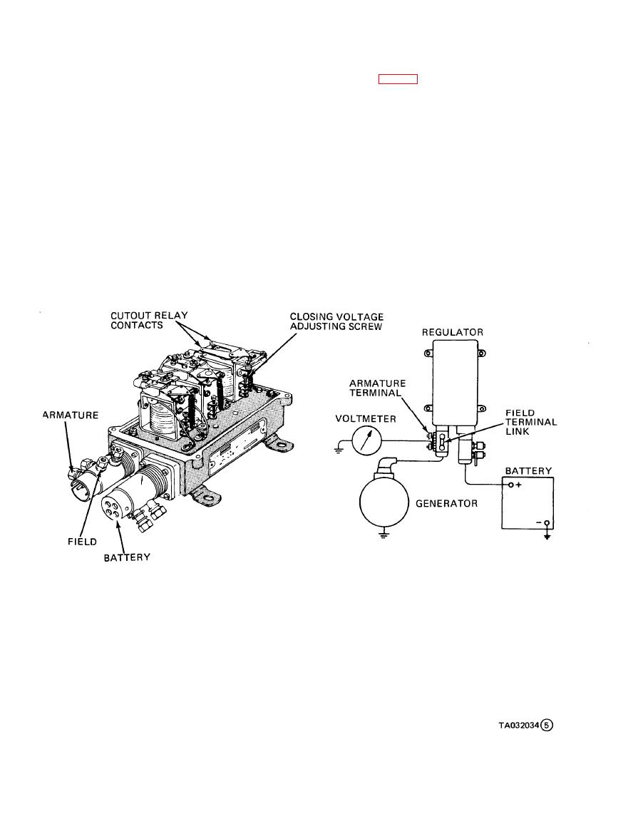
Figure 3-8. Voltage regulator adjustment. (sheet 5 of 5). |
|
||
| ||||||||||
|
|
 TM10-3930-634-34
(b) Loosen all inner and outer injector rack ad-
(g) Hold the gap adjusting screw and tighten
justing screws (fig. 3-15). Be sure all injector rack con-
lock nut. Recheck the gap and readjust as necessary.
trol levers are free on the injector control tube.
(h) Stop the engine and install the governor cov-
(c) Move the speed control lever to the full-fuel
er. Place the governor coveron the housing with the
positions.
pin of thespeed control lever projecting into slot of
(d) Adjust the rear injector rack control lever
differential lever.
first to establish a guide for adjusting the remaining
(i) Install screws finger tight. Pull cover away
injector rack control levers. Turn the inner adjusting
from engine and tighten screws.
screw down on the rear injector rack control lever until
(2) Positioning Injector Rack Control Levers.
a step up in effort to turn the screw driver is noted.
Properly positioned injector rack control levers with
This will place the rear injector rack in the full-fuel
the engine at full load will result in the speed control
position.
lever at the maximum speed position, the governor low
(e) Turn down the outer adjusting screw until it
speed gap closed, high speed spring plunger on the seat
bottoms lightly on the injector control tube. Then al-
in the governor control housing, and injector control
ternately tighten both the inner and outer adjusting
racks in the full-fuel position.
screw until they are tight.
(a) Disconnect any linkage attached to the speed
(f) To be sure the control lever is properly ad-
control lever.
1. CONNECT THE REGULATOR AS SHOWN ABOVE.
2. POLARIZE THE GENERATOR BY DISCONNECTING THE LINK IN THE FIELD CIRCUIT AT THE
ADAPTER, AND MOMENTARILY CONNECTING A JUMPER BETWEEN THE TERMINAL CONNECTED
TO THE GENERATOR FIELD AND THE BATTERY TERMINAL. RECONNECT THE LINK IN THE
FIELD CIRCUIT.
3. START THE UNIT AND SLOWLY INCREASE THE SPEED. THE CUTOUT RELAY CONTACTS
SHOULD CLOSE AT 26.0 VOLTS.
4. TURN THE CLOSING VOLTAGE ADJUSTING SCREW CLOCKWISE TO INCREASE THE CLOSING
VOLTAGE AND COUNTERCLOCKWISE TO DECREASE THE CLOSING VOLTAGE.
5. STOP THE UNIT.
Figure 3-8. Voltage regulator adjustment. (sheet 5 of 5).
3-12
|
|
Privacy Statement - Press Release - Copyright Information. - Contact Us |
