 |
|||
|
|
|||
|
Page Title:
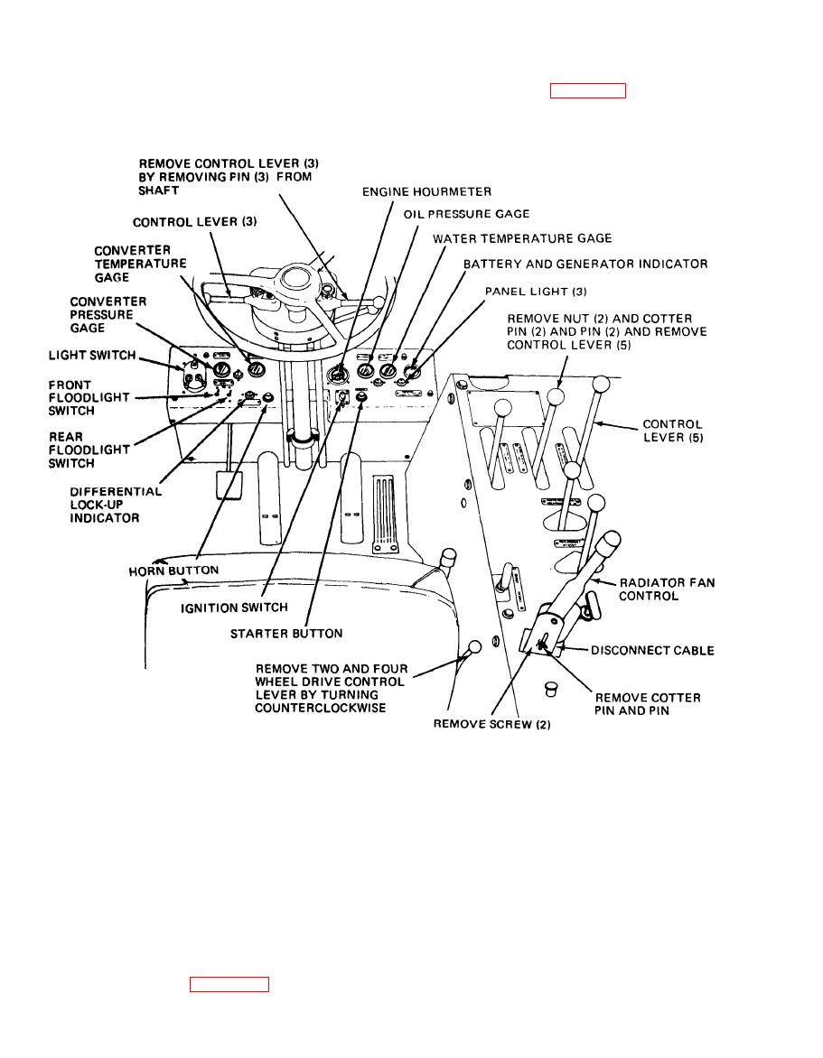
Figure 4-28. Controls and instruments, removal and installation. |
|
||
| ||||||||||
|
|
 TM 10-3930-634-12
c. Installation. Refer to figure 4-28 and install the
(2) Inspect the hydraulic control lever for cracks,
hydraulic control levers.
breaks, and loose hardware. Replace a defective control
lever.
TAG AND DISCONNECT ELECTRICAL LEADS AND REMOVE MOUNTING
NOTE:
HARDWARE AS NECESSARY.
TA031867
differential lockout control and remove it as follows:
(1) Remove spring at top of lockout pedal and dis-
a. General. The differential lockout control is located
connect line at bottom of lockout control valve.
on the firewall of the driver's compartment. When the
(2) Remove four screws and lockwashers attaching
lockout pedal is pressed, brake fluid VV-B680B is
pedal assembly to the cockpit floor. Remove pedal as-
forced to the lockout mechanism mounted on each
sembly.
differential. This action insures that each pair of driv-
c. Inspection and Service.
ing wheels turn together.
(1) Inspect the rubber boot and hoses for cuts and
|
|
Privacy Statement - Press Release - Copyright Information. - Contact Us |
