 |
|||
|
|
|||
|
|
|||
| ||||||||||
|
|
 TM 10-3930-634-12
TA031859
TA031860
removal and installation.
and test voltage regulator along with engine generator.
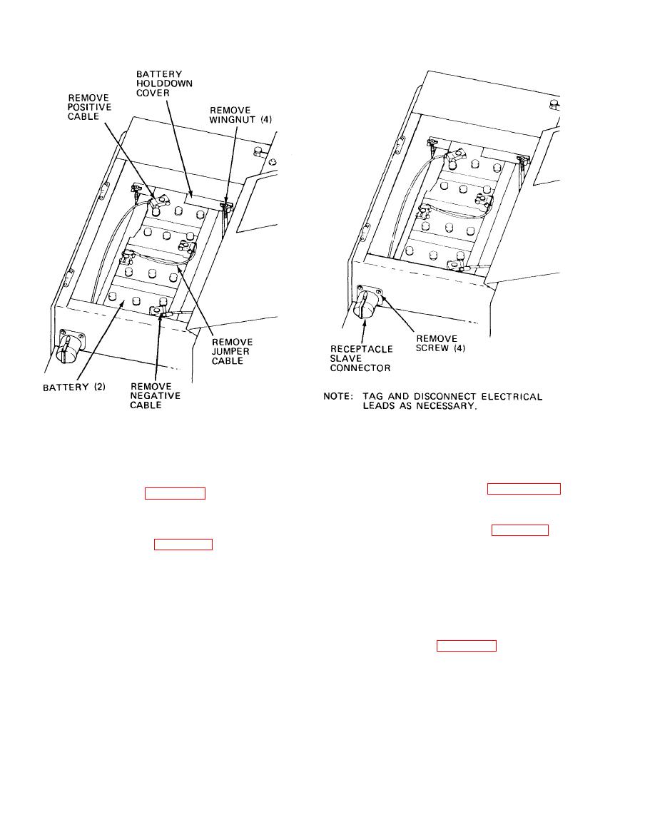
receptacle slave connector.
b. Removal. Remove right engine side panel. Tag
b. Inspection. Inspect for corrosion, broken or frayed
and disconnect electrical leads; refer to figure 4-22 and
wires. Replace defective parts.
remove the voltage regulator and bracket.
receptacle slave connector.
c. Cleaning and Inspection.
CAUTION
(1) Clean the voltage regulator and bracket with
When cables are replaced, insure that the
an approved cleaning solvent and dry thoroughly.
positive (+) cable is equipped with the
(2) Inspect bracket for cracks or breaks and in-
large battery post connector and that the
spect regulator for loose hardware, corrosion, and
negative (-) cable is grounded to the
damaged connectors. Replace all defective parts.
engine. When installing the receptacle,
place the positive (+) connector up in
d. Installation. Refer to figure 4-22 and install the
relation to its mounted position.
voltage regulator and bracket.
|
|
Privacy Statement - Press Release - Copyright Information. - Contact Us |
