 |
|||
|
|
|||
|
|
|||
| ||||||||||
|
|
 TM 10-3930-632-34
c. Check camshaft end play with a dial indicator.
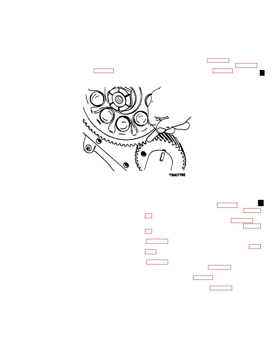
(2) If the gage will not enter, place a finger at the
junction of the two gears and tap the camshaft gear with
If end play is not between 0.003 and 0.007 inch, remove
a hammer. If vibrations can be felt in the large gear, the
the camshaft timing gear and replace the thrust plate
clearance is sufficient.
(14).
e. If gear clearance is too great or too small, the
d. Check the clearance between the camshaft and
gears must be replaced. Replace the gears only in sets.
crankshaft gears as follows:
f.
Install the gear cover (para 9-21).
(1) Force the teeth of the gears apart with a
g. Install the valves and valve tappets (para 9-13).
screwdriver. Attempt to insert an 0.0015 inch feeler
h. Install the cylinder head (para 9-9).
gage into the gap between the gears (fig. 9-31). If the
gage will enter, the clearance is excessive.
Figure 9-31. Checking Timing Gear Clearance.
Section XIII. CYLINDER BLOCK
a.
Remove the cylinder head (para 9-6).
9-38.
General
b.
Remove the intake and exhaust valves (para 9-
The cast iron cylinder block provides the four highly
c.
Remove the oil pan and oil pump (para 9-15).
machined cylinder bores in which the pistons ride. The
d.
Remove the gear cover and idler gear (para 9-
cylinder walls are surrounded by water passages to
enable the engine coolant to circulate and remove the
e. Remove the flywheel and flywheel housing
heat of combustion from the cylinders, thereby
maintaining the engine at proper operating temperatures.
f.
The cylinder block provides seats for the upper main
Remove the pistons and connecting rods (para
bearing shells and main bearing caps, as well as for the
camshaft bearings. Oil passages are also provided in
g. Remove the crankshaft and main bearings
the cylinder block. These passages direct lubricating oil
to the operating components of the engine. An oil
h. Remove the camshaft (para 9-35).
pressure regulator is installed in the cylinder block to
I.
Remove the bolts and lockwashers that secure
maintain the lubricant pressure at the required level. A
the backing plate (40, fig. 9-19) to the cylinder block;
rigid backing plate is secured to the front of the cylinder
remove the backing plate and gasket.
block. This provides a mounting for the hydraulic pump.
j.
Remove the plug (18, fig. 9-26) and gasket
(19) and remove the spring (21) and oil pressure
9-39.
Removal and Disassembly
regulating valve.
k. Remove the capscrews (11) and lockwashers
With the engine mounted on an engine overhaul
stand, proceed as follows:
Change 1 9-25
|
|
Privacy Statement - Press Release - Copyright Information. - Contact Us |
