 |
|||
|
|
|||
|
|
|||
| ||||||||||
|
|
 TM 10-3930-632-34
that the bearing surface has an almost cellular
(2) Position a connecting rod in its piston. Install
appearance. This is normal, and is not an
the piston pin; secure with the piston pin retainer ring
indication of impending bearing failure
(14, fig. 9-20).
e. Slide the piston rings (12) squarely into the
f.
Inspect all other parts for cracks, scoring,
cylinders in which they will be used. Check the ring gap
damaged threads, and other damage; replace damaged
with feeler gage. If the ring gap is not at least 0.010 inch,
parts.
file the rings to provide a larger gap. If the ring gap
exceeds 0.020 inch, rebore the cylinders (para 9-41) and
install oversize pistons and rings.
9-29.
Reassembly and Installation
f.
Install a piston ring expander on the bottom ring
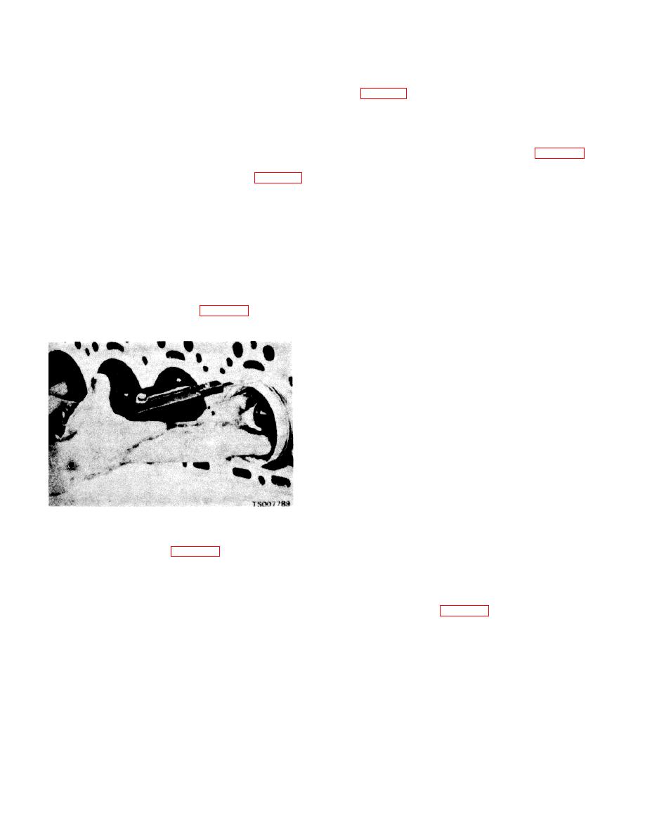
a. Check piston fit in the cylinder bore (fig. 9-25)
groove of a piston. Install the piston rings on the piston
using a piece of 0.0015-inch feeler stock cut 1/2 inch
with a standard ring expander tool.
wide. Dress the edges of the feeler stock with a stone to
g. Assemble the remaining pistons, connecting
remove burrs and feathered edges. The block and
rods, and piston rings.
pistons must be at room temperature when piston fit is
h. Install the assembled pistons and connecting
tested. Position the feeler stock midway between the
rods in the same cylinders from which they were
piston pin bosses. With the piston inserted about 2
originally removed. Use a ring compressor to compress
inches into the block, the feeler stock must pull from the
the piston rings. Lubricate the pistons and cylinder walls
block with 5 to 10 pounds pull. If the feeler stock does
with engine oil before installing the pistons. Wrap the
not offer enough resistance, perform the same test with
bottom end of the connecting rods with a cloth to prevent
a new standard size piston. If sufficient resistance is still
damage to the cylinder walls during installation.
not obtained, rebore the cylinders (para 9-41) and install
I.
Check the crank pin bearing journal-to-
oversize pistons.
connecting rod bearing clearance with plastigage. Lay a
piece of plastigage material on the crankshaft journal
and install the connecting rod bearing cap. Torque the
nuts to 35 to 40 ft. lbs. Remove the bearing cap and
compare the width of the flattened plastigage material
with the scale markings on the plastigage package to
determine the clearance.
The bearing-to-journal
clearance shall be 0.0007 to 0.0031 inch. If clearance is
beyond these limits replace the bearing and/or the
crankshaft as required.
j.
As an alternate method of checking crank pin
bearing journal-to-connecting rod bearing clearance,
install a piece of 0.0030-inch thick feeler stock between
the bearing and journal, and install the bearing cap.
Tighten the connecting rod cap bolts to 35 to 40 ft/lbs
torque.
Rotate the crankshaft to detect drag.
If
clearance is within tolerance, a definite drag will be felt.
Figure 9-25. Checking Piston Fit in Cylinder Bore.
Disassemble the rod cap and remove the shim stock. If
clearance is not within tolerance, replace the connecting
b. If new pistons (15, fig. 9-20) and piston pins
rod bearings and recheck the clearance. If clearance is
(16) are being used, press a new pin bushing (17) into
still not within tolerance, replace the crankshaft.
each connecting rod (21). Ream and hone the sleeve
k. Lubricate the crank pin bearing journals and the
bearings to 0.8596 to 0.8593-inch diameter.
sleeve bearings with engine oil. Install the cap on its
c. If the pistons and pins are not being replaced,
connecting rod (21, fig. 9-20) and crank pin bearing
check the clearance between the piston pins and the
journal; secure with the two bolts (18) and nuts (20).
sleeve bearings. Clearance must be between 0.0000
Tighten the nuts to 35 to 40 ft/lbs torque. Install the
and 0.005 inch. If clearance is not within this tolerance,
cotter pins (19).
press new sleeve bearings into the connecting rods and
l.
Secure the remaining connecting rods to the
ream and hone to provide the proper clearance. After
crank pin bearing journals.
honing, 75 percent of the sleeve bearing surface must
contact the piston pin.
d. When pins, bushings, and pistons of the proper
size have been found, assemble the pistons to the
connecting rods as follows:
(1) Heat the pistons and connecting rods in an
oven or in water to a minimum of 160 F.
9-19
|
|
Privacy Statement - Press Release - Copyright Information. - Contact Us |
