 |
|||
|
|
|||
|
Page Title:
Section X. PISTONS AND CONNECTING RODS |
|
||
| ||||||||||
|
|
 TM 10-3930-632-34
f.
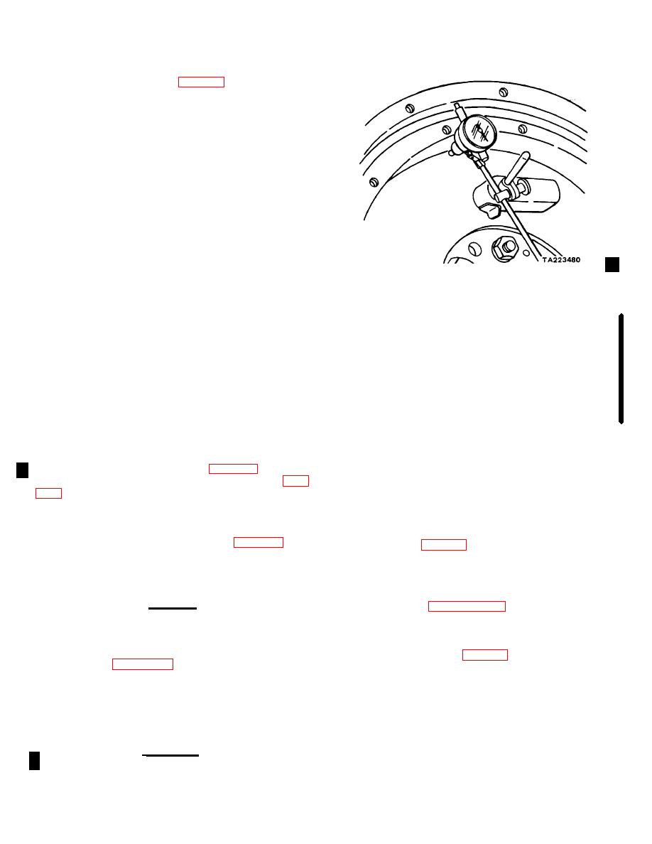
Check eccentricity of the flywheel housing bore
by mounting a dial indicator (fig. 9-24) and rotating the
engine through one revolution. If the housing bore is
eccentric more than 0.008 inch, loosen the flywheel
housing mounting bolts and tap the housing into its
proper position with a soft hammer. Tighten the bolts
and recheck eccentricity of the housing bore. If the
housing cannot be brought into true position, replace the
housing.
Figure 9-24. Checking Flywheel Housing Eccentricity.
Section X. PISTONS AND CONNECTING RODS
and use only in a well ventilated area. Avoid
9-26.
General
contact with skin, eyes, and clothes and don't
The engine uses aluminum pistons, each of which is
breathe vapors. Do not use near open flame or
fitted with three compression rings and one oil control
excessive heat. The flash point is 100F -
ring. The forged steel connecting rods transfer the force
138F. (38C - 59C). If you become dizzy while
from the pistons to the crankshaft. Close-fitting bearing
shells are installed between the connecting rod and the
using cleaning solvent, get fresh air immediately
crankshaft journals.
and get medical aid. If contact with eyes is
made, wash your eyes with water and get
9-27.
Removal and Disassembly
medical aid immediately.
With the engine mounted on an engine overhaul
stand, proceed as follows:
9-28.
Cleaning and Inspection
a.
Remove the cylinder head (para 9-6).
a.
Discard and replace the piston rings.
b.
Remove the engine oil pan and oil pump (para
b.
Clean all parts with cleaning solvent P-D-680
and dry thoroughly.
c.
Ream the ridge of the top of each cylinder
c.
Inspect the pistons for cracks, distortion,
bore with a standard ridge reamer.
Blow metal
broken ring lands and distorted grooves, loose piston
fragments from the cylinder with compressed air.
pin-to-piston fit and other damage; replace damaged
d.
Remove the two cotter pins (19, fig. 9-20) and
pistons. Refer to table 9-1 for wear limits.
nuts (20) that secure a bearing cap to a connecting rod
NOTE
(21); remove the cap and rod bearing (22).
Pistons and bearings are individually checked
e.
Push assembled piston (15) and connecting
and fitted to the cylinders at reassembly. Before
rod (21) up through the top of the block.
reassembly. the cylinder bores must be checked
CAUTION
as directed in paragraph 9-41.
While pushing the piston and rod from the block,
be very careful the connecting rod does not
d.
Inspect the connecting rods for cracks,
scratch the cylinder wall.
distortion, and other damage; replace damaged
connecting rods. Refer to table 9-1 for wear limits,
f.
Refer to figure 9-20 (items 12 through 21) and
e.
Inspect the bearing shells for scoring, wear,
disassemble the piston and connecting rod.
cracks, and other damage.
NOTE
NOTE
Disassemble the pistons and piston rods in sets,
New bearing shells are smooth and highly
and keep the sets together. Also, be sure each
polished. After a few hours of operation, the
piston and piston rod set is installed In the
bearing surface becomes a leaden grey and
cylinder from which it was removed.
develops minute craters so
WARNING
Dry cleaning solvent P-D-680 is toxic and
flammable. Wear protective goggles and gloves
Change 1 9-18
|
|
Privacy Statement - Press Release - Copyright Information. - Contact Us |
