 |
|||
|
|
|||
|
|
|||
| ||||||||||
|
|
 TM 10-3930-632-34
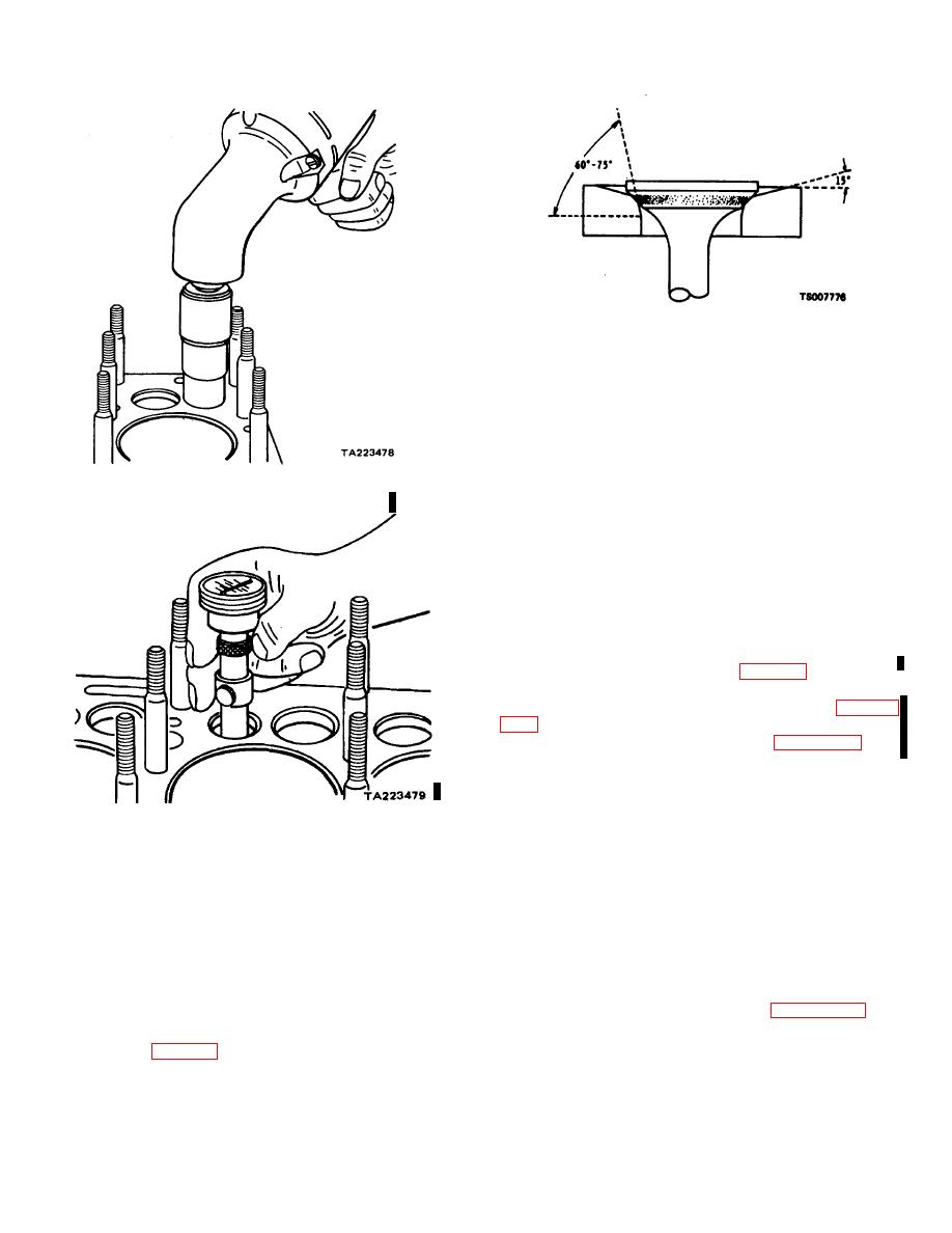
Figure 9-12. Narrowing Valve Seat.
k.
Inspect the spring retainer seat, spring
retaining locks, valve stem caps, and valve tappet
assemblies for cracks, scoring, overheating, and wear.
Replace damaged parts.
9-13.
Installation
a.
Position the valve tappet assemblies (8, fig. 9-
Figure 9-10. Grinding Value Seat.
6) in the engine block.
b.
Assemble the valves (1 and 2), valve springs
(5), spring retainer seats (9), and valve locks (7).
Compress the valve springs with a spring compressor to
install the valve locks. Turn the engine over as necessary
to allow each valve to move to the closed position before
attempting to install the valve parts. Make sure each
valve is installed in the guide from which it was removed.
c.
Temporarily set valve tappet clearance.
d.
Install the cylinder head (para 9-9).
e.
Operate the engine until it reaches operating
temperature. Adjust valve tappet clearance (para 9-
f.
Install the valve tappet cover (para 9-13.1).
9-13.1.
Valve Adjustment
a.
Operate engine until it reaches operating
Figure 9-11. Checking Valve Seat turnout.
temperature.
b.
Remove the nuts and washers that secure the
j.
After the valves and seats have been refaced
valve tappet cover to the cylinder block. Remove the
and reground, coat the seat lightly with Prussian blue and
valve tappet cover and gasket.
drop the valve into place oscillating it slightly to transfer
c.
With the engine at operating temperature and
the blue pattern to the valve face. This should show a
running at idle speed, set the valves for 0.012-inch
contact width of 1/16 to 3/32 inch, and should fall well
clearance as follows:
within the width of the valve face, leaving at least 1/64
(1) Check for proper 0.012-inch intake valve
inch on either side of the contact area. If the contact area
clearance by alternately passing an 0.011-inch and an
is greater than 3/32 inch, narrow the contact area by
0.013-inch flat feeler gage between the head of the
grinding the outside diameter of the seat with a 15 stone
adjusting screw and intake valve stem (figure 9-12.1).
or by grinding the inside diameter of the seat with a 60
(2) If an 0.011-inch feeler gage moves freely
back and forth in the gap when the valve is not being
or 76 stone (fig. 9-12). After the seat area is corrected,
lifted and an 0.013-inch feeler gage binds at
touch the seat lightly with the original grinding stone to
remove the burred or feathered edge.
Change 1 9-9
|
|
Privacy Statement - Press Release - Copyright Information. - Contact Us |
